This thread has been locked.

If you have a related question, please click the "Ask a related question" button in the top right corner. The newly created question will be automatically linked to this question.

ADS1115: ADS1115 reading drops across the current sense resistor when using internal isolated 24V supply

Part Number: ADS1115
Other Parts Discussed in Thread: AMC1300

Hi,

I'm been struggling with this issue for a while now and would like to ask for your help.

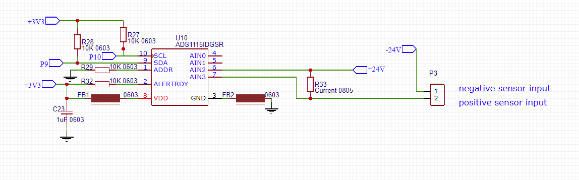
I'm using ADS1115 IC to read a voltage across the current sense resistor for 4-20mA sensor.

I designed a step up from 3.5V to 24V isolated flyback converter (on the same board) and connected its output as in the schematic attached. Current sense resistor is 49.9 ohms.

When I test it, the current reading (or the actual voltage reading drops slightly) as the current increases. It reads 19.63 mA instead of 20 mA. But its okay when I apply 4mA.

When I take exactly same two boards and have the step up 24V and current sense resistor on one board and ads chip on the second board. And connect wires across the current sense resistor to the pads of the second board where current sense resistor should go and the reading is good! I get 20mA reading, no less. And 4mA is still the same. Also I tried moving the current sense resistor to the second board and the reading is still good. I tried using 24V externally and the reading is good. The reading is dropping only when I have 24V on the same board. 

Do you think they interfere? How does the reading drop? I measured the actual voltage drop across the current sense at both situations (good and bad reading) and the voltage drop is the same. So its not losing the voltage. it must be something happening in ADS chip. I'm so confused.. If it was getting extra resistance on the way to the ADS chip then extra resistance would make overall voltage higher and the reading would be higher, not lower. If i had extra parallel resistance then I would see the lower voltage drop across the current sense resistor but the voltage is exactly the same with internal or external 24V.

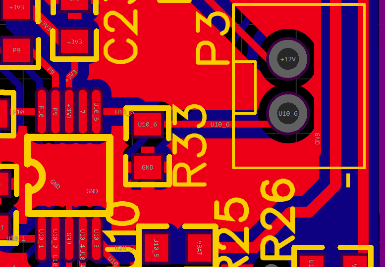
One theory is the my layout is not correct. I have a step up in between the ADS chip and the current sense chip. And I should have a current sense resistor first and close to ADS chip. But still why does it work when I connect the same step up externally? I can redesign the layout and order new boards but I'm not sure if that is an issue.

Also I tried switching the boards and replacing the ADS chip. Didn't help.

Arghh.

Thank you!

Emilija

Current applied (mA) The actual reading (mA)
4 3.99
8 7.99
12 11.89
16 15.77
20 19.63

  • Emilija,


    The ADS1115 was not designed to measure voltages that are isolated or floating. For the ADC to work the input voltage should definitively be within the GND to VDD. This is described in the Recommended Operating Conditions section of the datasheet.

    While this measurement may work to some extent, if the input floats beyond the supplies, the voltage sampling may leak and cause a measurement error.

    If you do try making a current sense measurement, I would try using a low-side current measurement using a common-ground. Looking at the schematic, I would also remove the ferrite beads (FB1 and FB2) and replace them with shorts. That inductance may add some error and may create spikes in the supply because of digital current contribution to from Ldi/dt.


    Joseph Wu
  • Hi Joseph,

    I made some progress and discovered that adding a snubber to 24V step up helped to reduce the error. I think I had huge transient that causes ADS chip to fail. I had some other issues with another circuit and I think its because of the transients. I improved my layout and waiting for a new board. 

    How can I use a common ground? Have you got an example please? If i connect the 24V step up to ground, than I would get 24V across the sensing resistor? 

    Interesting that ferrite beads would create spikes. How does it work? I thought that ferrites were added to reduce the noise. I added ferrites because there were fitted in the module which uses ADS1115 IC.

    Thank you.

    Regards,

    Emilija

  • Hi Joseph,

    I tested and it works with a common ground!

    That means I don't need an isolated power supply.

    Thanks!!

  • Emilija,


    I'm glad that you were able to get the measurement to work. If you needed to measure an isolated or floating supply, I might recommend using an isolation amplifier. Perhaps something like an AMC1300 which might be used for measuring shunt resistors across some isolation.

    Relating to one of your previous posts, I suggested removing the ferrites through ground to remove the inductance from the line. Generally ferrites will help for more analog functions, where the current is more continuous. However when there are digital currents, the result may add more spiking to the supply lines. Because the voltage across an inductor is related to L(di/dt), the sharp changes in digital currents can cause the voltage to spike as well.


    Joseph Wu
  • Hi Joseph,

    I don't need an isolated power supply anymore because I use a common ground now.

    Is it okay to connect 24V supply as in the diagram I sent you?

    Do you mean by digital currents from communication I2C? The rest of it is analog.

    Thank you.

    Regards,
    Emilija
  • Hi Joseph,

    I've got a question about the layout. So I placed the current sense resistor very close to the ADS pin. What about 24V supply and the current sensor input? At the moment I have a current sensor input close to the ADS pin but 24V step up is a bit further away. There is a micro controller for other purpose in between the ADS and 24V but it will be off because its for another version board.

    Is it better to have 24V boost close to ADS IC? Or will it cause some noise to ADS IC because of the switching?

    Current loop should still provide the correct current because that's an advantage of the current sensor and 24V step up is further away to avoid the noise. Is this correct?

    Thanks,
    Emilija
  • R33 - current sense resistor and P3 is the current sensor input,

  • Emilija,


    I'm still unsure about the connection you have in one of your previous posts. I'm not sure how your connection of the node labeled as "-24V" and the analog ground are related.

    IF the ground of your analog section can be connected to this "-24V" node, AND the supply of the analog section can be limited to about 5V above this "-24V" node (for the VDD supply), AND the voltage of R33 doesn't go 0.3V above the VDD, then this should work.
    It would be best to give a better block diagram of what it is you're measuring. If you're not using an isolated supply, it's likely this could be ok.

    When I mentioned the digital currents, the ADC itself has digital currents (in addition to the digital communication). This ADC is a delta-sigma type and has an internal clock that samples the input at a 250kHz rate. It takes many input samples to create a single output data that comes out anywhere from 8SPS to 860SPS (depending on the DR setting you have programmed).

    I would guess that it's better to have the 24V supply further away for EMI. In general, I'd use a small input RC filter for the input. This would give any high frequency EMI a low impedance path to ground. The current loop should provide the correct measurement as long as you have a good ground plane and connection from the ground plane to the supply return. It's a little hard to tell how you have the ground connected here. At the end of the ADS1115 datasheet, there's a generic description of Layout Guidelines.


    Joseph Wu
  • Hi Joseph,

    Sorry for the confusion. -24V is an actual ground. I had it labeled as -24V before because I was using an isolated DC-DC.

    The maximum current will be 20mA and I'm using 49R9 resistor so the maximum voltage across the resistor will be ~1V. What would be the best resistor for 20mA reading to get the best accuracy? I think as long as below 2V then don't need extra gain? Do you mean that I should keep the maximum voltage of 0.3V across R33 when I read 20mA?

    Should I use RC filter right next to R33 current sense resistor? Should I just add 100nF cap next to it? Would it help with an accuracy?

    I use a 2 layer board with a ground flood. I don't have a separate ground plane.

    I found that measurements were inconsistent (varied by 0.5mA). Possibly because of the wrong layout (current sense resistor being further away) and the no common ground? New design was ordered and will test it hopefully beginning of next week.

    Thank you.

    Regards,

    Emilija

  • Emilia,


    Ok, I think I understand the ground connection.

    The 49.9Ω resistor should be fine. I imagine that you'd want to use the most accurate resistor that you can get for the measurement. I don't think you'll need additional gain unless you want it. My comment about 0.3V is to make sure the input voltage is within the supply. If you imagine that the supply goes from 0V ground for GND to 5V supply for VDD, you don't want any input to go to below -0.3V or above 5.3V.

    I would put filtering near the input of the ADC. It shouldn't matter too much that the sense resistor is further away. If you want, layout a series resistance (and use 0Ω) and a cap (but not populate it). You can evaluate that later. The input current to this ADC is rather low so having a longer length of wire shouldn't be much of a problem. However, you want to be careful with the layout in the sense that you don't want to create large loops to create an antenna for EMI. In the previous iteration of your board, my suspicion is that the error you were seeing comes from not having a common ground.


    Joseph Wu
  • Hi Joseph,

    That's great, thanks! I'm using 0.01% accurate resistor.

    Is the schematic below you have in mind? I think series resistor will affect the measurement? What RC filter values should I try?

    Regards,

    Emilija

  • Emilija,


    Actually R1 would be on the opposite side of C1. The source of the signal is the measurement of R33. The ADC wants to see the RC filtered output.


    Joseph Wu
  • Emilija,


    Also, filtering depends on the data rate that you choose. I would generally use an RC bandwidth of 10x of the data rate. For example, if you're using a 128SPS data rate, you want a filter bandwidth of 1.3kHz or so. I'd probably choose something like 1.2kΩ and 100nF. I'd use an upper limit of 5kΩ for the series resistor.

    Again, that's something you can play with after the fact to see if it helps in the filtering and noise performance


    Joseph Wu
  • Hi Joseph,

    Thanks, I will try for the next board.

    Will R1 have an impact on the ADS voltage reading? It will have some voltage drop and could affect the accuracy. What is the pin current? Maybe just a capacitor will help?

    Thank you.

    Regards,

    Emilija

  • Emilija,


    There will be a small amount of voltage drop because of the input impedance of the ADC. So the current depends on input voltage value. This input impedance has a differential and common-mode component described in the datasheet (page 16 for the description and page 7 for the values).

    For this and similar devices, the input impedance comes from charge being pulled away as an input sampling capacitor gets discharged. In this type of system, a large series resistance can additionally impact the sampling of the input. With a large series resistance, the sampled value may not reach a settled value (again in the figure on page 16, that would be 1/250kHz or 4us). For that reason, I like to keep the input resistance below 5kΩ.


    Joseph Wu
  • Hi Joseph,

    Ok, I will add the footprint for the next board. Or cut the track and add the components for the existing board.

    Thank you for your support.
    Emilija