This thread has been locked.

If you have a related question, please click the "Ask a related question" button in the top right corner. The newly created question will be automatically linked to this question.

DAC37J84

Other Parts Discussed in Thread: DAC37J84, DAC38J84

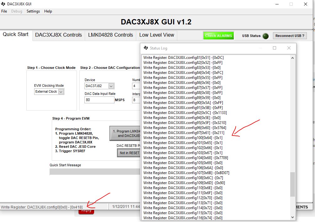
I used DAC37J84 and Intel altera fpga to transmit data. The CGS and ila phases seem to have passed, but my DA output waveform has many burr, but the frequency is corresponding. I read the value from 0x6c and found there is an error.Then I will see SYNCB on the fpga end will have a cycle of pulling down and then pulling up. May I ask why?

  • BZ,
    we will look into this.

    -Kang
  • BZ,
    The JESD204B is a state machine. This means the same behavior and same error, depending on the previous state, may have different meaning and interpretation of root-cause. You have to be specific on your error. Please read back register Config 100 (0x64) to config107 (0x6B) to get a better understanding of the problem. You mentioned that CGS and ILA phases seem to have passed, please advise how you arrived at such conclusion.

    The cycle of pulling down and pulling up generally means the CGS have passed, but there may be code errors in the actual data (i.e. 8b/10b errors). You may need to try to improve your signal integrity of the data link.

    Another common error is the RBD (release buffer delay) adjustment. The release buffer is used to absorb difference in lane skews (including skew from your FPGA IP). If the RBD is not adjusted optimally, the sync signal will not be released properly. You will have to fine tune the RBD value in the 0x4B register. If you see RBD buffer overflow error, you will need to adjust the RBD until you reach optimal delay time to absorb all delay variations.

    -Kang
  • Thank you for your reply. The problem has been solved. My interpolation configuration is wrong.
    I used dual-mode,LMF=421,HD=1.everthing is OK,I can see the two-way waveform I sent in the FPGA at the output end.
    but now I want to use Quad-mode,LMF=442,HD=0,I modified the value of the associated LMF register,The same modification was made on the FPGA,But now the result I have observed is that the ila stage has not been passed,The result of reading registers 0x64, 0x65, 0x66, 0x67 is 0x2100.It looks like link configuration error, But I carefully checked the value 0x4b-0x4e,I don't think my configuration is wrong,May I ask what other aspects I should pay attention to?
  • Hi BZ,

    the ILAS sequence are generic for each lane except for lane ID. You will need to pay attention to 0x46 to 0x48 register to ensure the lane ID for the link are programmed correctly. I have drafted a ILAS sequence spreadsheet that you may use to double check.

    You may also set sync_request_link0 and error_reporting_link0 registers to have the bit5 (link configuration) disabled. This way the SYNCB~ signal will not react to any ILAS sequence error and still proceed with link up. Give it a try to see if you can get the link established. This way you can know for sure there are something wrong with ILAS.

    ILAS typically is used as an link identifier at the start-up. We have not really find it being used extensively in many of our customers applications.  6327.DAC3xJ8x ILA Sequence.xlsx

    0550.DAC3xJ8x JESD204B Sync Request and Error Report.pptx

  • Today, I successfully passed the ila stage,However, I have a question. In the ILA sequence file you gave me, HD=1, but the four-way data input I used, shouldn't HD be 0?And I used the ila stage that HD=0 just passed, but now there is a new problem,That is, after the ila stage is passed,I read the register 0x64, the value of 0x65 is 0, which proves everything is correct, but there is no waveform coming out in the output end of my DA, my IOUTB and IOUTD are connected to the ground, 0X1A is set to 0x25, but I think this does not affect the output of IOUA and IOUC,I don't know what else I need to do,As mentioned before, after I switched back to the dual-mode configuration, the output of IOTA and IOUTC was normal,My linear speed is 1600m, dacclk is 640m, and the interpolation is 8x without PLL. Can you give me a correct configuration
  • BZ,

    I recommend that you use the DAC38J84 EVM GUI to generate the configuration files needed for your application.

    http://www.ti.com/lit/zip/slac644

    see below for my interpretation of your application.

    you mentioned linear speed is 1600M? I am not sure what you mean by linear speed. I am assuming line rate. Since you are only use 4211 mode with 2 DACs, you rate may be half at 800Mbps.

    you may generate the configuration file, double click on the register details, and right click to save into a text file.