This thread has been locked.

If you have a related question, please click the "Ask a related question" button in the top right corner. The newly created question will be automatically linked to this question.

DDC114: Get a higher input range

Part Number: DDC114

Hi team,

We are facing an issue that we want to have a current input 100uA.

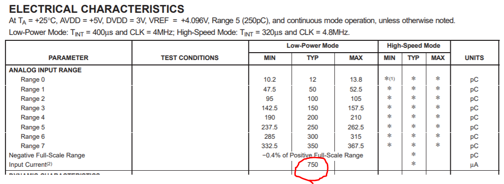
By data sheet, maximum input current =350pC/50us=7uA 

Yet, there's still a input current spec 750uA.

Is it possible to have a higher input current (100uA)?

If yes, how could we do that?

If no, is there any TI device with higher input range?

Thank you.

Best Regards,

Cindy

  • Hi Cindy,

    Your interpretation of the DS is correct (the 7uA). The 750uA is only from the risk of damaging the device perspective.

    Nevertheless, not all is lost... One thing (that probably doesn't work for you) is that in the 350pC/50us the assumption is constant current. Nevertheless, you could have a 1us, 20uA pulse and it would still work, from an input saturation perspective. Note: There may be a challenge with the input response of the device. The device would try to take as much of that current as possible but due to the BW/input amplifier response, part would actually get stored in the input parasitic capacitance which would flow into the device after that first 1us and effectively accounted later. This has limits/would have to be tested and performance may not be exactly the same, but we do have customers that use the DDCs with pulsed input currents, where the peak current exceeds the "DC" computed limit.

    After the above, the only options are to modify externally the input configuration to deal with the current. One approach is to short couple or more DDC channels so the current is split between them. There are some limitations to that but it seems to work on some experiments we did  (work under progress). Nevertheless, this may not be enough for your 100uA. Another approach is to use a resistor divider where part of the current is routed to ground and part onto the device input. We are also checking this but it does also seem to work although you do need to take into account on your calculations that the input impedance of the device is not zero (you can measure it by applying a current and measuring the input DC bias voltage).

    The person working on these experiments/configurations is currently ooo but please write to ddcxxx-support at list.ti.com if you want to be updated later...

    Regards,
    Edu