This thread has been locked.

If you have a related question, please click the "Ask a related question" button in the top right corner. The newly created question will be automatically linked to this question.

DAC8742HEVM: DAC8742h SPI communication

Part Number: DAC8742HEVM
Other Parts Discussed in Thread: DAC8742H, ADS8166, DAC8741H

Hello,

I configurate modem setting

REEST :                                      0x07 0x00 0x01

MODEM_STATUS Register :      0x20 0xdc 0x24

CONTROL Register :                  0x02 0x80 0x4c

MODEM_IRQ_MASK Register : 0x21 0x7f 0x3f

MODEM_CONTROL Register :  0x22 0x00 0x4d

FIFO_LEVEL_SET Register :     0x25 0x00 0xff

PAFF_JABBER Register :          0x27 0x00 0x02

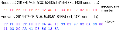
I send data 0x23 0x00 0x11 for transmit data and send data 0xa4 0xff 0xff 0xff 0xff 0xff for receive data.

So I receive right data 0xa4 0x01 0x11.

I want to make hart frame and must send much of data at the same time.

I send first data 0x23 0x00 0x11, and send second data 0x23 0x00 0x77.

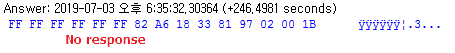
But I just receive first data(0xa4 0x00 0x11). I send data 0xa4 0xff 0xff 0xff 0xff 0xff, 0xff 0xff 0xff for receive data. 

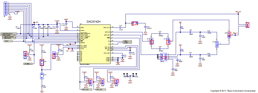
I have been connected MOD_IN and MOD_OUT and it configure ST MCU(master) and DAC8742h(slave).

I do not know if modem settings are wrong or if I sent the wrong data.

  • Hi Mayikol,

    Do you have a schematic or diagram of how you have the hardware connected?

    Thanks,
    Paul
  • Hi Paul,

    I use external reference voltage and SPI communication connect my MCU

  • Mayikol,

    The intended use is to load the TX FIFO then to toggle the RTS bit such that the device begins to go through the contents of the FIFO. I suggest you begin with the same MODEM_CONTROL configuration but with bit 0 set to 0. Then, load the TX FIFO with all of the data you wish to transmit. If sending a packet larger than the FIFO the mechanics of the FIFO level interrupts come into play.
  • Mayikol,

    Any update?
  • Hi Duke,

    I solved the problem about sending and receiving data. But I have one more problem.

    When receiving more than 16 bytes, only 16 byte data size received and the remaining data lost.

    I think if I read data consistently, there should be no problem even if overflow occurs.

    In the above answer, you said that the mechanics of the FIFO level interrupts come into play.

    You mean that I control MODEM_IRQ_MASK Register or SPI Interrupt Handler of MCU?

    Same problem occurs in DAC8742H EVM S/W.

    Thanks,

    Seo

  • Mayikol,

    I would suggest referring to page 18, section 7.4.3 of the datasheet. Both transmit and receive FIFOs are only 16-locations deep which means if you are not consistently clearing out the FIFOs they will eventually fill and any additional data will be lost.

    The best method to leverage the FIFOs is described in the first paragraph on page 19 - which essentially describes using the IRQ pin along with the FIFO_M2D_LEVEL bit in the MODEM_STATUS register to keep track of the level of the FIFO and ensure that it does not overflow. The FIFO level which will trigger this event is programmed by the FIFO_LEVEL_SET register, which contains bit-fields to set these thresholds for both transmit and receive FIFOs.

  • Mayikol,

    I see that you have rejected the reply. Can you please follow up with details concerning where your remaining confusion is?

  • Duke,

    Thank you for your help. I solved the problem about receive data by reading Modem_Status_Register and using delay timing. 

    I don't use IRQ pin yet, because I did not set it in hardware. Ultimately, it is timing that solves this problem. One character takes 9.16ms.

    So I give the delay time each reading character about 10ms. 

    Now I try to transmit data. Mod_out signal transmit, but does not receive from the slave.

    Before transmit data.

    FIFO_LEVEL_SET Register : 0x00, 0x0F

    MODEM_CONTROL Register  : 0x00, 0x08

    I transmit data of 15 byte size. And I set RTS bit.

    MODEM_CONTROL Register  : 0x00, 0x09 (I give delay times as much as the data size.)

    After MODEM_CONTROL Register  : 0x00, 0x08

    I checked that analog signal is normal and modem status register is normal.(0x40, 0x24)

    I attach my hardware configuration.

    I think register configuration is wrong. Because there was no problem with the same hardware and frame in UART communication. Now the signal is

    transmitted but not received from the slave module. I tried setting the parity bit but it was useless.

  • Mayikol,

    By default without modifying any of the SPI register contents the device is configured the same in either SPI or UART interface modes. The only difference, as you have eluded to, are timing considerations since the SPI interface can be significantly faster than the UART interface.

    I think it would be worthwhile to check what is happening on the IRQ pin to ensure that the FIFOs are properly loaded for the packet transmission.

  • Mayikol,

    Any news on this topic?

  • Duke,

    I am not sure what the exact problem is. I checked H/W test, but it was not hardware problem. I think the conclusion is f/w problem. 

    I checked the hart frame by secondary master using serial monitoring program.

    And when I send same frame as the primary master, the tx signal goes out but no response.

    In the above the picture, answering data is the Tx data of primary master reading from secondary master.

    If it is normal, the slave sends response signal but there is no response.

    If it is a timing problem, the data is damaged or missing. But when I check tx data in secondary master by serial monitoring, no problem. Also when I read MODEM_STATUS register, it is no error.

    Is there any example code or other way to simply test the hart frame? 

    I'm using DAC8741h and ADS8166 now. 

  • Mayikol,

    The only real sample code we have prepared for this device is a C header file which contains bit-field and register address definitions to help customers get to programming with the device quickly. However since the chosen MCU platform can vary greatly in this space, we did not generate any platform-specific C driver files. The closest thing would be the EVM GUI along with the USB-2-ANY.