Hello,
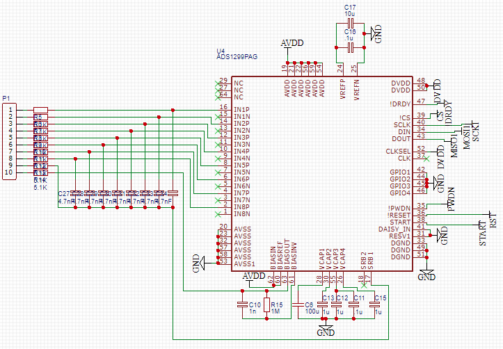
I have designed a breakout board for the ADS1299 according to the schematic below.
The negative pins are floating, and I want to reference all the positive pins to SRB1.
I want BIAS to drive the bias electrode with the inverted common-mode signal.
The breakout board has been connected to a Raspberry Pi, and the SPI comms has been successfully programmed and tested using a signal generator.
On channel 1, it can accurately record a 1mV sine wave (that is the lowest amplitude the signal generator (SG) can produce).
To do this, I connect IN1P to the positive output of the SG, and I connect both SRB1 and BIAS to the negative output.
When tested on a human head, the signal never settles. Instead its jumps around and hits the max and min rails.
I have tried a number of register configurations (in particular changing and trying different combinations of config3, misc1, bias_sensp, bias_sensn and the individual channel registers).
None of them have so far given me accurate results.
I would appreciate it if someone could provide me with the correct register configuration to correctly implement the electrode setup in the schematic below.
Or, maybe there is a hardware issue which I have not spotted, but it is odd that I can accurately record mV signals from a SG when SRB1 and BIAS are shorted.
Thanks for your help.