This thread has been locked.

If you have a related question, please click the "Ask a related question" button in the top right corner. The newly created question will be automatically linked to this question.

DAC3171: The noise base of DAC3171 monotone signal is much higher than that of AD9743 monotone signal.

Part Number: DAC3171
Other Parts Discussed in Thread: DAC3174

Dears:

Could you kindly help to check the schematic and parameters, since we use our DAC3171 to replac ADI's AD9743, there is some issue about our design:

1. DAC3171's Parameters:

Address 0x00    Data    0x46FC

Address 0x02    Data    0x3F80

Address 0x03    Data    0x0001

2. Issues:

Monotonic signals are sent by the FPGA,and the before design using ADI's AD9743.  TI and ADI's bit width is 10 bit, both clock and power are the same.

1) The noise base of DAC3171 monotone signal is much higher than that of AD9743 monotone signal.

2) DAC 3171 has a lower noise base and keeps the full range of DAC when it is used in two-tone and four-tone signals.

3. Pls. refer the below schematic and ware forms.

a) Schematic:

DAC3171原理图.pdf

b) DAC3171_1tone 

c) DAC3171_2tone 

d) DAC3171_4tone 

e) AD9743_1tone 

Pls. give some advice about our design, we want to replace ADI successfully.

Pls. help us.

  • Hi Liam,

    We are looking at your question and will get back to you.

    Regards,

    Neeraj

  • Hi Neeraj:

    Pls. refer the below diagram for your reference.

  • Hi Luck,

    I think the DAC is not configured properly for 7 bit mode and it is only receiving the Upper 7 bits of data and lower 7 bits are not getting into the device as result you see higher noise floor. To configure the DAC in 7 BIT interface mode please try the following register write sequence.

    The first column is the register address and second column is the values written to the registers.

    DAC3174
    0x00 0x4EC
    0x01 0x401E
    0x02 0x3F80
    0x03 0x1C71
    0x08 0x6000
    0x09 0x8000
    0x0A 0xF080
    0x14 0x0000
    0x01 0x401E
    0x01 0x403E
    0x01 0x401E

    Regards,

    Neeraj

  • Dear Neeraj:

    Using your demo can not  configure properly for 7 bit mode too.

     I see you write DAC3174 and we use DAC3171.

    Is it the same about the part?

    Pls. give some advice.

  • Hi Neeraj

    It still doesn't work with your recommended settings.

    Do you have any more advice of this issue?

    Regards

    Thomas

  • Dear Neeraj:

    Customer tested their board found the below 2 issues, and want to know the below issues whether is the root can not configure the DAC in 7 BIT interface mode. Pls. kindly help to give some advice about the below issues.

    1. customer configures config1 (reg 0x01) as 0xC01E (bit15 set to 1, i.e. turn on iotest mode), and find that the low 14bit (iotest_results) read-back value of config4 (reg 0x04) is not all 0. The value changes every time the power is restarted, but it is not all 0 each time. The read-back value of bit4 (alarm_from_iotesta) of Config5 (reg 0x05) is 1, which means that the test has errors.

    2.  Customer found the reading register's bit6 value( 0x05 alarm_dataclk_gone) is always 1, and it's possible dataclk is loss or having mistake.

    However, tesing the clock is normally from DAC3171 testing.

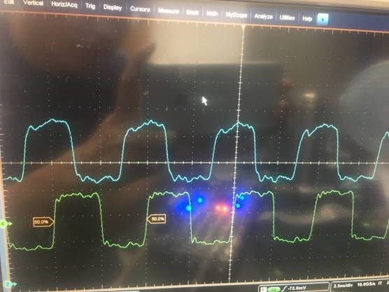
    The waveform as below picture:

    1). Green signal is data_clk, and blue signal is one bit of 7bit data.

    2). The every bit of 7bit data is 1 when the clock is rising edge, and when the clock is updown edge the every bit is 0.

    3). Clock frequency is 200MHz.

  • Was your issue solved?

    Regards,

    Neeraj

  • Hi Neeraj:

    The issue is not solved, pls. kindly help to check my reply.