This thread has been locked.

If you have a related question, please click the "Ask a related question" button in the top right corner. The newly created question will be automatically linked to this question.

ADS8681EVM-PDK: Analog Input Circuit

Part Number: ADS8681EVM-PDK
Other Parts Discussed in Thread: ADS8681, ADS8638EVM-PDK, ADS8638, ADS8568EVM-PDK, ADS8568

HI Staff
Evaluated using the ADS8681EVM-PDK,
Please let me know because there is an unknown point

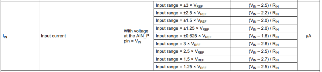
Q1: When the input is open, 2V can be seen at the input terminal.
    Is this not a problem?

Q2: Also, please tell us the basis for this 2V.

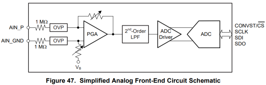
    * Can you provide an equivalent circuit for the analog input section?

Q3: The signal to the analog input terminal is driven by an external opamp,
    A 470ohm Damping Resistor is connected to the output of the opamp.
    Is this not a problem?

Q4: When using the USB-GUI software of the ADS8681 EVM-PDK, when the power is first turned on,
    All CH-1 measurements were to measure 0 every time.
    It went back after repeating the CH setting several times, but some cause
    Do you understand?
    There is no particular problem after the second power on.

best regards
cafain

  • Hi Cafain,

    Answer 1:  This is not a problem. ADS8681 datasheet has mentioned that "If the analog input pin (AIN_P) to the device is left floating, the output of the ADC corresponds to an internal biasing voltage. The output from the ADC must be considered as invalid if the device is operated with floating input pins. This condition does not cause any damage to the device, which becomes fully functional when a valid input voltage is applied to the pins" in page 24 (7.3.1 Analog Input Structure). Also, the Electrical Characteristics table in the datasheet as below shows this information about this bias voltage(e.g. (~2.5V bias voltage for +/-3Vref range).

    ADS8681 has an integrated analog front-end (AFE), the simplified input circuit is shown with a bias voltage(~2.5V for +/-3Vref range) in Figure 47 also as below, the input signal is biased to the appropriate common-mode voltage level for proper operation of internal ADC core. When there is an available input signal on ADC input, the available signal will dominate it, if the input is floating and no any signal, the bias voltage will be observed, the converted voltage/code may be different for different front-end RC filter if a pull down resistor is used before filter. Since this ADC supports true bipolar input signals using a single +5V power supply, the internal biasing cannot be done to provide a zero offset at ADC output when the inputs are left floating. One of the advantages of this input stage is that it offers a 1-MOhm constant resistive input impedance.  This makes the inputs relatively easy to drive (in most cases) without additional driver amplifiers or buffers. General switched-capacitor input structure ADC needs a lot of cautions to design front-end amplifier and RC filter, any improper amplifier and RC selection will lead to large error to settle the signal on internal sampling capacitors and will get worse performance result, but the front-end design for this ADS8681 with such integrated AFE will be much easier, and the ADC can be driven directly without any external amplifier because the AFE and ADC driver have been integrated into these ADC.

    To emphasize again, this bias voltage was known when the ADC was designed for this structure and these benefits. This is very common for the ADCs with such integrated AFE and input structure

    Answer 2:  Please see the simplified input circuit in Figure 47 also as above.

    Answer 3:  It is better to show your schematic here. As mentioned in answer 1, this ADC does not require a specific driving circuit to settle the signal and drive it. Hence, your 470ohm resister should be fine if it is inserted in series with the ADC input and my understanding is correct.

    Answer 4:  I would like to check on the EVM but I'm on a business trip. I will try to check with peers and get it back to you. Please allow me for a delay.

    Best regards

    Dale

  • Hi, Dale-san

    Thank you for explaining in detail.
    I understand the content you have received.
    As for Question 4, I will evaluate it a little more.
    There may be my operation mistake.
    If you have another question, we will contact you.

    Thank you very much.
    Answer 4: I would like to check on the EVM but a business trip. I will try to check with peers and get it back to you. Please allow me for a delay.
    best regards
    cafain
  • Hello

     ADS8638EVM-PDK: Can I get a FPGA source (Verilog) code for ADS8638?

    or  ADS8568EVM-PDK: Can I get a FPGA source (Verilog) code for ADS8568?

    Because currently using ADS8638, so try to provide ADS8638,Thank you.

  • Hello ,

    As my colleague has answered  your query as below, the software is no longer available. I will close this thread. Thanks.

    https://e2e.ti.com/support/data-converters/f/73/t/816895

    Hi Cafain-san,

    Please let me know if you need further support on ADS8681. Thanks.

    Regards,

    Dale