This thread has been locked.

If you have a related question, please click the "Ask a related question" button in the top right corner. The newly created question will be automatically linked to this question.

ADS1015: ADS1015 ADC is not acknowledging any data after address

Part Number: ADS1015

Hi All,

I am trying to interface the ADS1015 ADC with an STM32 microcontroller through I2C bus. ADS1015 is acknowledging the address but not acknowledging any data sent after the address.

Please let me know if this is this the correct procedure for writing to the ADS1015 ADC in single shot mode when OS is single?

1. Started transmitting, "START",

2. Accessing Device Address 0x48 

3. Acknowledgment for Device Address after a 9th bit is received.

4. Accessing Config Register Adress Pointer 0x01;

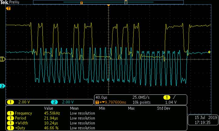
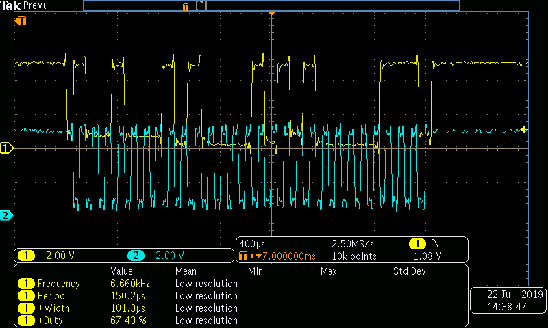
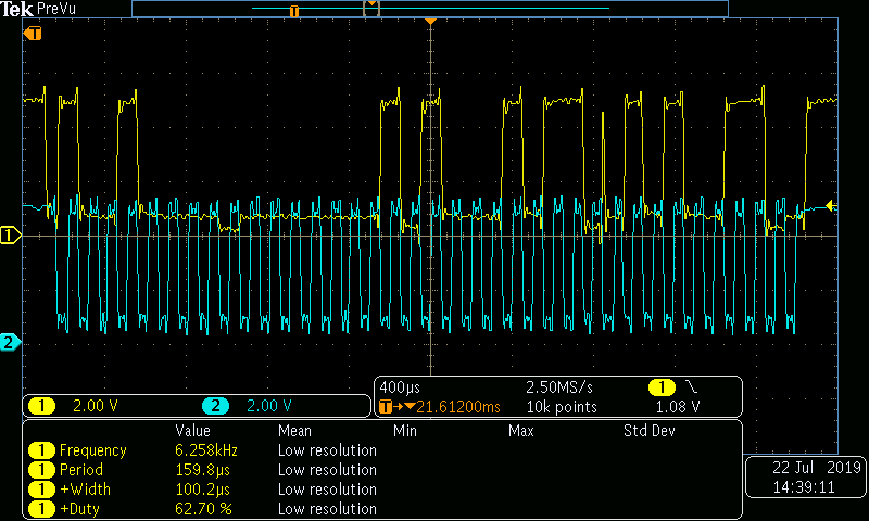
5. Acknowledgment for Config Register Adress Pointer after a 9th bit is not received.

On view the oscilloscope it shows a HIGH bit after the 8th bit of Register Address Pointer. Please check the attached image.

  • Shubhanshu,


    I've been looking at your post for a while and I don't see what could be wrong. It looks like you've set up everything in the I2C communication correctly and the device doesn't respond as I would have expected. I would have thought that the result would look like the communication shown in Figure 16.

    The device ACKs the first address byte, but does not ACK the address pointer. There's no I2C restart, and it should just ACK this second byte.

    Is there anything else on the I2C bus? Have you set up the ADS1015 with a different address to see if it responds differently? Again, I think this should work, and don't see anything that could be a problem. It's strange to see the device respond the address, but not respond to the second byte. Are you measuring the I2C right at the pins of the ADS1015? I just wanted to see if there might be other noise or delay that might affect the resulting response from the device.

    Anyway respond back to the post with some answers to my questions and we'll see if we can figure this out.


    Joseph Wu

  • Joseph,
    There is no other device connected to the I2c bus.
    On setting up with different address 0x49, there is nothing changed on the oscilloscope screen, adding the image for it.
    I also shortened the length of the wire, but still, it's responding the same.
    This ADS1015 is placed on the Air Quality 5 board with MiCS-6814 sensor.

  • Shubhanshu,


    Just to check, can you send a schematic of how you have the device set up? I also wanted to confirm that the microcontroller and the ADS1015 are operating on the same voltage and have a common ground. If the two are on different voltages then they may respond to different threshold levels. It does seem that the device has already ACKed the address, but if there are other disparate levels, there still may be communication problem.

    Just looking at the scope shots, there is some variation in the output voltage of the SCLK, and I just wanted to confirm that the levels are direct. Additionally what values are you using for the I2C pull-up resistors? I don't see it here, but if you have too weak of a pull-up resistor, there may also be problems.


    Joseph Wu

  • Hi Joseph,

    I've attached the image of the controller board and sensor, in which you can confirm the connections.

    I'm using the ST discovery board which is having an stm32f030r8 controller.

    I'm using I2c at 100 KHz clock speed, which is mostly required 2.2K ohm resistor.


  • Shubanshu,


    I'm sorry I didn't get back to you earlier. I was out of the office at the end of the week.

    I'm still not sure what the problem is. The only thing that I can think of is that the supplies of the microcontroller and the device aren't matched up and the I2C levels aren't compatible. I still would have expected the setup to work, but for now, I would run the Air Quality board from the 3V supply to start (presuming that the ST microcontroller is running off of 3V as well).

    Also, do you have more than one Air Quality board and more than one Discovery board to try?


    Joseph Wu

  • Hi Joseph,

    I've tried with a regulated power supply providing the 5V and making ground common, I didn't see any difference in the waveform on the oscilloscope and issue has remained the same.

    I don't have any extra sensor board.

  • Shubhanshu,

    I'm sorry that I missed this last post. Were you able to solve this communication problem? I'd made some suggestions, but I don't see anything wrong with the scope shots that you provided in your previous posts.

    I'll close this post for now, but if you continue to have problems with this issue, post back and we'll work on it again.

    Joseph Wu

  • Hi Joseph,

    If nothing is wrong in the scope shots then why address pointer is not giving me acknowledgement, because in software I've coded according to the datasheet.

  • Shubanshu,

    I'm sorry I didn't get back to you, but I'm out of the office.

    It's a bit hard to see all the timing for the I2C for the ADS1015 with your one scope shot. There are quite a few parameters to verify, but my guess is that the device has somehow seen an I2C stop after the address. Again I don't see it on your scope shot. 

    Just as a test, I've used a Total Phase Aardvark controller to communicate with an ADS1015. Below, I show what happens when the I2C talks to the device to read the configuration register. Here's an scope shot of the communication:

    First, here is the write to access the configuration register:

    Then, here is the read from the register:

    In this transaction, I get 8583h as the reading, which is the expected default. I posted these plots just to show that the I2C communication should work. I don't see anything different in yours except that it looks like your device has stopped communicating. It may be NACKing your second byte because it's might have somehow received a I2C stop.

    Look through my scope shots and see if there's anything that might be different. I would note that I do have a long period of time between the first shot and the second shot, but that's because I don't have the fine control of timing with this controller. This shouldn't affect your communication because your problem is in the second byte. 

    Joseph Wu

  • Hi Joseph,

    My question is are you writing any parmeter values to the configuration register? As the sensor board and datasheet says that we need to write some configuration values then after that we can read from the conversion register.

  • Shubanshu,


    I didn't have any problems writing to or reading from the device configuration register. Here's an example that I tried:

    Starting with the device at power up, I read from the configuration register. First, here's the write to the device, indicating the configuration register with the address pointer:


    Then the read from the configuration register itself. This reads 85 83:


    Next, I write to the device. This includes the address pointer of 01 and is a total of 4 bytes (including the I2C address). I write 8B 53 to the device:


    Finally, I go back and read the configuration register again. Here's the write to the device again including the address pointer.:


    Here is the resulting read which is 0B 53:


    The 0 in the first byte means that I've started the conversion with the new configuration, and that the conversion is in progress. This is what it looks like in the control software:


    I would also point out that when using the device in continuous conversion mode, a write to the device may not take place immediately. The write to the configuration register does not take place until after the conversion in progress completes. If you write to the device and immediately read it back, you may get the current configuration setting until the conversion completes and the new configuration is finally set up.


    Joseph Wu

  • Shubhanshu,

    I had asked this earlier, but have you tried to run the board from a 3V supply? If you're trying to run the device from 5V and the microcontroller runs from 3V, then the I2C thresholds will be different between the microcontroller and the device.

    Make sure the supply for both the microcontroller and the device are the same or a level translator may be required between the two.

    Joseph Wu

  • Shubhanshu,

    I haven't heard from you for a while so I thought I'd check to see if you've solved your I2C communication problem. I didn't have any definitive answer of what the problem was, but I thought it might be because of a mismatch in the I2C voltage levels between the master and the device. I did give an example of how you would communicate with the device, writing to it and reading back the register value.

    I'll close this post for now, but if you continue to have problems with this, post back and it will keep the thread active.

    Joseph Wu