


Sampling rate = 500Hz
Gain = 1
Test signal
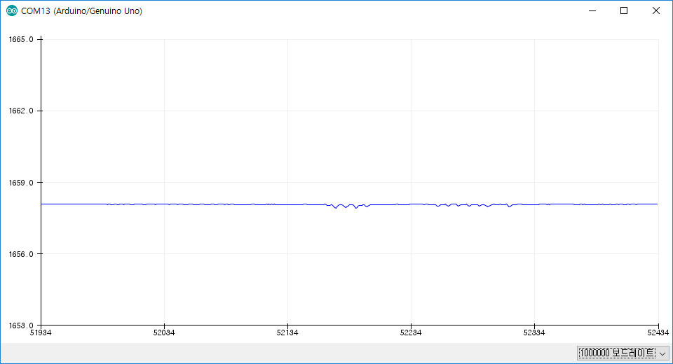
VDD/2(3.3V/2 = 1.65V)

±50mV
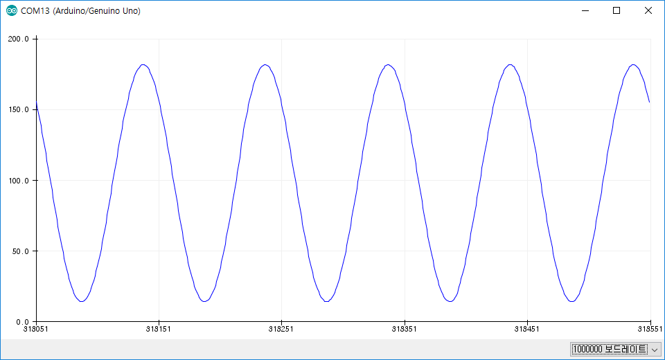
±100mV

±200mV

±300mV
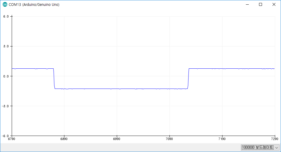
> Saturation....
I don't know why....
please help me
Sampling rate = 500Hz
Gain = 1
Test signal
VDD/2(3.3V/2 = 1.65V)
±50mV
±100mV
±200mV
±300mV
> Saturation....
I don't know why....
please help me


