This thread has been locked.

If you have a related question, please click the "Ask a related question" button in the top right corner. The newly created question will be automatically linked to this question.

ADS1232: Resistive Bridge Measurement

Part Number: ADS1232
Other Parts Discussed in Thread: ADS122U04, ADS1220, , ADS1235, ADS1261, ADS122C04

Hi All,

I am looking into the use of the ADS1232 or something similar for a Resistive Bridge Measurement. The sensor i am using has a resistance range of 3 ohms (normal unstretched configuration) to 22 ohms (fully stretched). I will be using a microcontroller to interface with the analog-to-digital converter. I also have a supply voltage of 3.3V or 5V. So a unipolar supply is preferred. Some initial experiments show better results with constant current excitation, and i can see that some of the TI chips support this as a built-in feature. I am able to communicate via most methods (SPI, UART etc) so i don't have a preference. I have also looked at the ADS1220, ADS122U04 and others. 

I am new to resistive bridge measurements so would greatly appreciate some advice on the pros and cons of this ADC over others in your range. Higher resolution is preferred as the ultimate goal of this sensor is to characterize it for position measurements. 

Thanks for your time.

Kind Regards,

Zoran

  • Hi Zoran,

    Are you building your own bridge using a strain gauge?  The strain resistance does not tell me the output voltage (or range) to be measured.  Usually a bridge will have some value of sensitivity where full-scale output is rated in mV/V of excitation.  Have you designed your bridge so that you know what the output of the bridge is with respect to the sensitivity?  

    The decision to choose which ADC will work best will depend on the noise of the converter and the method of excitation.  The noise of the converter will determine the resolution of the ADC but this does not translate directly to noise-free counts of the bridge.  The bridge will output a voltage with a specific range relative to the excitation.  Many times the range of the bridge is 1/4 or less of the full-scale range of the ADC, reducing the resolution of the bridge output.

    Although the ADS1220 and ADS122U04 can measure bridge output, these devices do not offer the lowest noise.  The ADS1232 and ADS1235 are low-noise ADCs for bridge applications that are excited by a voltage.  The ADS1235 adds the option for built in operation of AC excitation.  A similar device to the ADS1235 is the ADS1261 which can also provide current excitation.

    The ADS1261 offers the most flexibility, but to fully determine which device to use will depend on how the bridge performs and resolution of measurement required.

    Best regards,

    Bob B

  • Hi Bob,

    Thanks for the prompt reply. The sensor is a custom flexible strain sensor (not a typical strain gauge) which can be integrated into clothing and other fabrics, so when it is stretched, there is a change in resistance. We have some okay results with constant current excitation and a single opamp, but not in a wheatstone bridge configuration. There is very little range in the output to produce a good working resolution with the sensor stretch. I was  hoping that one of these TI devices, in a bridge configuration would produce better results. 

    Kind Regards,

    Zoran

  • Hi Zoran,

    I may be of more help if I know something more about the bridge output and the desired resolution.  If we think in terms of volts, what is the maximum output of the bridge for a given excitation voltage?  With respect to the output voltage, what is the desired resolution?  For example, the maximum bridge output is 20mV for a 5V excitation with the desire to resolve to 400nV (which equates to 50k points of measurement resolution for the output range).

    Best regards,

    Bob B

  • Hi Bob,

    I apologize for the late reply. At this early stage I am looking to build a circuit for this flexible resistance sensor. The application is to ultimately use this for position measurement, so a measurement resolution of 1k points would be more than enough, given it is an elastic sensor. To set me on the right path, would a resistive bridge circuit be more appropriate for this sensor or something similar to a 2 wire RTD approach?

    Regards,

    Zoran 

  • Hi Zoran,

    This is somewhat difficult to answer.  In the end it will really depend on the excitation source and the output voltage from the sensor.  In the case of a Wheatstone bridge, the output swing will depend on the resistance range of the leg elements.  Probably the simplest configuration would be the use of the constant current source similar to a 2-wire RTD.  The circuit to use would be in this guide:

    http://www.ti.com/lit/an/sbaa275/sbaa275.pdf

    The ADS1232 does not have an excitation current source, but the ADS1220 (SPI), ADS122C04 (I2C)  or ADS122U04 (UART) does.  You could set up the measurement similar to what is shown in Figure 7 of the above document on page 10.  You could use something line 250uA of current with a reference resistor of 6.8k Ohms to make a ratiometric measurement.  You could also use the device PGA and a gain of 128 to increase your measurement resolution.

    Best regards,

    Bob B

  • Hi Bob,

    Thank you for this reference document and advice. I just ordered an ADS1220 breakout to test with. I will try the 2-wire RTD configuration you mentioned.

    Given that this sensor well eventually be worn on the human body, the increasing temperature of the sensor could negatively impact the output. Would it be possible to use the same ADC to test the performance of a Wheatstone bridge configuration with current excitation? 

    Regards,

    Zoran

  • Hi Zoran,

    You could also try current excitation of a bridge configuration, but if you had trouble with voltage excitation you will most likely see issues with current excitation.  It is the sizing of the legs of the bridge that will determine the range of the sensor output.  Current excitation will be limited to the total current output of the ADS1220 while still meeting the compliance voltage of AVDD-0.9V.  In other words, the voltage drop across the bridge from excitation current is limited to AVDD-0.9V otherwise the constant current source can no long remain constant.  Most likely your best bridge output will be from voltage excitation as the bridge can be excited by AVDD while still maintaining a ratiometric measurement.

    If temperature affects the sensor, I would suspect you would see an error in any type of measurement scheme.  Your measurement result will only be as good as the stability of the sensor itself.

    Best regards,

    Bob B 

  • Hi Bob,

    Thanks for you support so far. I have implemented the schematic shown below with the flexible resistor in place of the RTD. I am using a breakout board from Protocentral (schematic shown below also).

    The supply voltage AVDD and DVDD is 3.3V. The reference resistor is currently a 5k Ohm precision resistor with +-10ppm/degC (I couldn't find a 6.8k Ohm version with quick delivery). The excitation current is set to 250uA. The gain is set to 16.

    This setup sets the Vref voltage to 1.25V, which is not the ideal common-mode voltage of 1.65V as stated in the ADS1220 datasheet.

    As mentioned earlier, the flexible sensor has a resistance range of 3-22 ohms. In its outstretched state Vin(max) = Vflex = Rflex*IIDAC1 = 22ohms*250uA=5.5mV.

    The max Gain at Vref = 1.25V is (1.25V/5.5mV = 227). Obviously cannot be achieved with the ADS1220.

    Below are the register settings i have used and have managed to capture some of the raw conversion data.

    The issue (not sure if it is an issue though) is that i am receiving large negative values of the output code from the ADS1220. For example:

    Not touching the sensor (at rest): -889267942

    Fully stretched sensor: -889986462

    Do you have any suggestions on whether I am on the right track with this? There is definitely a lot of data points in the full range of flexible sensor stretch (over 700k points).

    Regards,

    Zoran

    Register Config:

    m_config_reg0 = 0x38; //AINP=AIN1, AINN=AIN2, Gain 16, PGA enabled 
    m_config_reg1 = 0x84; //DR=330 SPS, Mode=Normal, Conv mode=continuous, Temp Sensor disabled, Current Source off 
    m_config_reg2 = 0x44; //Vref REFP0 and REFN0, NO 50/60Hz rejection, power open, IDAC (250uA)
    m_config_reg3 = 0x20; //IDAC1 (AIN0), IDAC2 disabled, DRDY pin only 

  • Hi Bob,

    I was just wondering if you had some time to consider my previous message and related questions?

    Regards,

    Zoran

  • Hi Zoran,

    I apologize for the delayed response as I was out of the office for a few days and just returned today.

    I'm not quite sure why you picked a gain of 16, when you could be using a gain of 128.  Also, the conversion result is output in binary 2's complement.  You must make sure that you properly sign-extend this value from a 24-bit value to a 32-bit value.  For instance, 0xFFFFFF is -1 decimal.  You should also determine if you have an internal offset of the ADS1220 by first checking the conversion result with the mux setting where AINP and AINN are shorted to (AVDD-AVSS)/2.  You should subtract the value returned from future conversion results.

    It would be much easier for me to determine what is happening if you sent me the raw hex value being returned from the ADS1220 as I have no idea what your decimal values are truly representing.  Also, make sure that the IDAC current is flowing through the AIN1 to AIN2 input as it would appear that the current is flowing from AIN2 to AIN1 based on the negative values.

    Best regards,

    Bob B

  • Hi Bob,

    No problem at all. I went with a gain of 16 to minimize noise but i just increased that to 128. I also increased the current to 1mA as the previous system was using this effectively with this sensor. I did realize i was dealing with a conversion result in binary 2's complement. I updated my code to properly sign-extend the value from 24-bit to 32-bit. 

    Thanks for this feedback. I did notice this in the datasheet (checking the conversion result when AINP and AINN are shorted to (AVDD-AVSS)/2) and subtracting this from future conversions. I will implement this shortly and see how it looks.

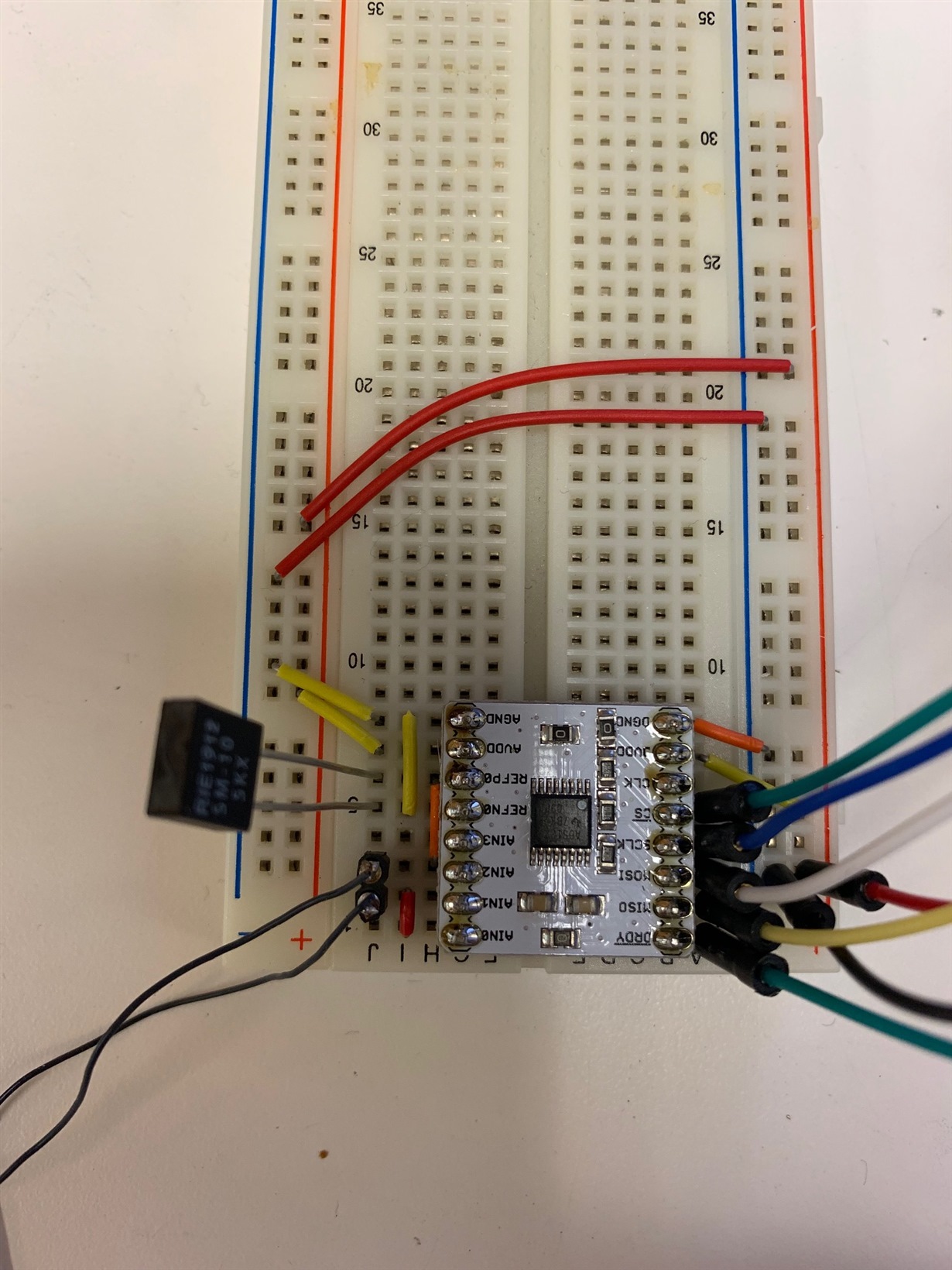
    Everything you have mentioned seems great. In regards to the negative values, I don't see a reason for this. Below is a photo of my connections. I think it is all correct. Can you see anything wrong here?

    No problem. I will records the raw hex values and send them through also.

    Thanks for your support Bob.

    Regards,

    Zoran

  • Hi Zoran,

    I don't see anything wrong in the assembly of the prototype, but keep in mind that it is difficult to get high levels of precision using a breadboard circuit.  I do believe you have a problem in number conversion.  The largest possible negative value (or negative full-scale) occurs at 0x800000 or decimal -8388608.  The values you are reporting are way beyond the ability of the ADC closer to a 32-bit value.

    If the most significant bit of the 24-bit result is '1' then the value is negative, otherwise the result is positive.  Make sure that you are capturing all 3 bytes of the conversion result and that the bytes are in the correct byte order.  Feel free to send me a code snippet of the data capture and storage to memory.  If you have scope or logic analyzer shots of the communication we can verify that you are interpreting the result correctly in your code.

    Best regards,

    Bob B

  • Thanks for the prompt reply Bob.

    It's really puzzling that the conversion values i am getting are negative. I managed to correct the issue (i believe) with the greater than 24-bit values. I had an issue with the byte order and also sign-extend the value. Below is a code snippet of the code that reads the data from the ADS1220.

    Any other ideas on the negative values would be greatly appreciated.

    Regards,

    Zoran

    Below is an image of the latest data:

    ----------------------------------------------------

    long Read_WaitForData()
    {
    static char SPI_Buff[3];
    long mResult32 = 0;
    long int bit24 = 0;
    int i;

    if((m_drdy_pin) == 0) // Wait for DRDY to transition low
    {
    m_cs_pin = 0; //Take CS low
    Delay_us(100);
    for (i = 0; i < 3; i++)
    {
    SPI_Buff[i] = SPI3_Read(SPI_MASTER_DUMMY);
    }
    Delay_us(100);
    m_cs_pin = 1; // Clear CS to high

    bit24 = SPI_Buff[0];
    bit24 = (bit24 << 8) | SPI_Buff[1];
    bit24 = (bit24 << 8) | SPI_Buff[2]; // Converting 3 bytes to a 24 bit int
    /* sign extend data */
    if (bit24 & 0x800000)
    bit24 |= 0xff000000;

    mResult32 = bit24;
    }
    return mResult32;

    }

    ------------------------------------------------------

    In main below, i call the function and store the data to transfer over USB HID.

    adc_data = Read_WaitForData();

    //StoreADC(adc_data,0);
    writebuff[0] = ((adc_data >> 24) & 0xFF);
    writebuff[1] = ((adc_data >> 16) & 0xFF);
    writebuff[2] = ((adc_data >> 8) & 0XFF);
    writebuff[3] = ((adc_data & 0XFF));
    Delay_ms(10);

    -----------------------------------

    On the Windows GUI side, i assembly the data as:

    unsigned char Datal[] = {buf[3], buf[2], buf[1], buf[0]};
    memcpy(&ADCVal, &Data, sizeof(Data));

  • Hi Bob,

    I added the following function for the offset calibration and it gives me a result of -587183. So a raw conversion value of -8170078 would subtract the offset value to become -7582895.

    I have not done anything with the two's complement yet, as the conversion value is still negative and i'd like to try to figure out why this is happening.

    Regards,

    Zoran


    I first set the MUX to (select_mux_channels(MUX_DIV2);  //Configure for AINP and AINN shorted to (AVDD + AVSS) / 2)

    ---------------------------------------

    char CalibrateADS1220()
    {
    int i = 0;

    while(i<100)
    {
    if((m_drdy_pin) == 0) //Wait for DRDY to transition low
    {
    CalibData += Read_WaitForData();
    i++;
    }
    }
    CalibData = CalibData/100;

    select_mux_channels(MUX_AIN1_AIN2);
    Delay_ms(200);
    return 1;
    }

    -----------------------------------------------------------------

    Below is the latest offset data conversion:

  • Hi Bob,

    Attached is the SPI data exported from a logic analyzer.

    Regards,

    ZSPI Capture.csvoran 

  • Hi Zoran,

    When troubleshooting a system, it is always best to check individual pieces instead of looking at the whole system at once.  If we look at the logic analyzer data we see a pattern that appears to be negative in value (131 XXX XXX), but part way through we see a positive value 3 XXX XXX (time 0.099002).  The positive pattern appears again at time 0.176004, 0.308004, 0.616006, 0.627018, 0.737008, 0.770007, and at 0.814008.

    One piece of information is missing from the logic analyzer data, and that is the time when DRDY transitions from high to low.  As you are reading direct from the ADS1220 and not using the RDATA command, it is quite possible that the data is becoming corrupted while reading the result.  When reading the conversion result directly as you are doing, you are only looking to see if DRDY is low, and not when DRDY is transitioning from high to low.  When using this method, you should always monitor the transition state and not just looking for DRDY to be low.  If DRDY should transition in the middle of the read cycle, the data will be corrupted by the writing of the new conversion result to the output buffer.  If instead you use the RDATA command, the automatic update of the conversion result to the output buffer is blocked until the RDATA command has completed.

    I would suggest that you issue the RDATA command instead of the current method you are using.  If you want to read the data directly, then you should use an interrupt driven system.  If you must use a polling method you may want to make sure that you are monitoring for the transition of DRDY in  Read_WaitForData() instead of just checking to see if it is low.  The reason is your are reading approximately every 10ms, but you are getting a new conversion result every 3.03ms.  During this time DRDY will be low as the conversion result has not been read for several conversion cycles.  DRDY will only pulse high for a very short time signaling a new completed conversion.  If you read data during this update period the result will be corrupted.

    Best regards,

    Bob B

  • Hi Bob,

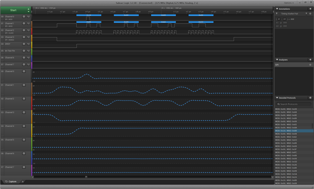
    I apologize for the late reply. I was traveling over the last week. Thank you for the feedback. SPI Capture5.csvI have redeveloped the code and considered the timing of the ADS in greater detail, and followed some of the example code that TI provides. I have setup an interrupt for the DRDY, and set a flag when DRDY goes low. In the main loop, I check to see if this flag is set and then read data from the ADS. I read the data by sending the RDATA command first. Below is a screenshot of the logic analyzer with the interrupt implementation and also the data i have captured over USB and plotted.

    I have also tried not to use an interrupt and simply read data from the ADS with the RDATA command. This approach seems to produce more corrupted data, as you can see below.

    I am seeing an improvement in the data using the RDATA command and an interrup, however a lot of data is still being corrupted. I am wondering if you have any ideas why this is happening?

    I attached the source code implementation for your reference.

    Kind Regards,

    Zoran

    HID_Read_Write.c
    /* 
     * Project name:
         HID_Read_Write (USB HID Read & Write Test)
     * Copyright:
         (c) Mikroelektronika, 2014.
     * Revision History:
         20140924:
           - initial release (FJ);
     * Description:
         This example establishes connection with the HID terminal that is active
         on the PC. Upon connection establishment, the HID Device Name will appear
         in the respective window. The character that user sends to ARM from the HID
         terminal will be re-sent back to user.
     * Test configuration:
         MCU:             STM32F407VG
                          http://www.st.com/st-web-ui/static/active/en/resource/technical/document/datasheet/DM00037051.pdf
         Dev.Board:       clicker 2 for STM32 - ac:clicker_2_STM32
                          http://www.mikroe.com/stm32/clicker-2/
         Oscillator:      HSI-PLL, 120.000MHz
         Ext. Modules:    None.
         SW:              mikroC PRO for ARM
                          http://www.mikroe.com/mikroc/arm/
     */
    #include <built_in.h>
    #include "ADS1220.h"
    
    char readbuff[64];
    char writebuff[64];
    char SPI_MASTER_DUMMY;
    int dFlag = 0;
    sfr sbit m_cs_pin at GPIOE_ODR.B2;        // SPI chip select
    sfr sbit testpin at GPIOE_ODR.B3;     // TEST PIN
    //***********************************************************************************/
    //InitMCU(): Initialises all of the required general purpose IO and SPI.
    //Parameters: None
    //***********************************************************************************/
    InitMCU()
    {
       Delay_ms(100);        // Delay after power-up for ADS1220 voltages to stabilise.
       //Setup Digital pins for SPI
       //GPIO_Digital_Output(&GPIOE_BASE, _GPIO_PINMASK_13);   //Reset pin
       //GPIO_Digital_Output(&GPIOE_BASE, _GPIO_PINMASK_8);   //SPI CS
       GPIO_Config(&GPIOE_BASE, _GPIO_PINMASK_2,
                _GPIO_CFG_MODE_OUTPUT | _GPIO_CFG_PULL_UP); //SPI CS
       GPIO_Digital_Input(&GPIOE_BASE, _GPIO_PINMASK_1);   //Interrupt pin (Don't Pull-up)
    
       GPIO_Digital_Output(&GPIOE_BASE, _GPIO_PINMASK_3);   // TEST PIN
       //GPIO_Digital_Output(&GPIOE_BASE, _GPIO_PINMASK_12);   //LED
    
       m_cs_pin = 1;                    // Deselect ADS1220
       testpin = 1;
       
       // Setup SPI. Use SPI3 module at PORTB[10:12]
       //SPI3_Init_Advanced(_SPI_FPCLK_DIV16, _SPI_MASTER  | _SPI_8_BIT |
       //                   _SPI_CLK_IDLE_low | _SPI_FIRST_CLK_EDGE_TRANSITION |
       //                   _SPI_MSB_FIRST | _SPI_SS_DISABLE | _SPI_SSM_ENABLE | _SPI_SSI_1,
       //                   &_GPIO_MODULE_SPI3_PC10_11_12);
       // Setup SPI. Use SPI1 module at PORTA[5:7]
       SPI1_Init_Advanced(_SPI_FPCLK_DIV16, _SPI_MASTER  | _SPI_8_BIT |
                          _SPI_CLK_IDLE_low | _SPI_FIRST_CLK_EDGE_TRANSITION |
                          _SPI_MSB_FIRST | _SPI_SS_DISABLE | _SPI_SSM_ENABLE | _SPI_SSI_1,
                          &_GPIO_MODULE_SPI1_PA567);
    
       //Setup External Interrupt
       SYSCFGEN_bit = 1;                    // Enable clock for alternate pin functions
       SYSCFG_EXTICR1 = 0x00000040;         // Map external interrupt on PE1
       EXTI_RTSR = 0x00000000;              // Set interrupt on Rising edge (none)
       EXTI_FTSR = 0x00000002;              // Set Interrupt on Falling edge (PE1)
       EXTI_IMR |= 0x00000002;              // Set mask
       NVIC_IntEnable(IVT_INT_EXTI1);   // Enable External interrupt
    }
    /* ADS1220 Initial Configuration */
    void ADS1220Config(void)
    {
       unsigned char Temp;
       // Register 0
       ADS1220ReadRegister(ADS1220_0_REGISTER, 0x01, &Temp);
       // clear prev value
       Temp &= 0x00;
       Temp |= (ADS1220_MUX_1_2 | ADS1220_GAIN_128);
       // write the register value containing the new value back to the ADS
       ADS1220WriteRegister(ADS1220_0_REGISTER, 0x01, &Temp);
       
       // Register 1
       ADS1220ReadRegister(ADS1220_1_REGISTER, 0x01, &Temp);
       // clear prev DataRate code;
       Temp &= 0x00;
       Temp |= (ADS1220_DR_330 | ADS1220_CC);                // Set default start mode to 330sps and continuous conversions
       // write the register value containing the new value back to the ADS
       ADS1220WriteRegister(ADS1220_1_REGISTER, 0x01, &Temp);
    
       // Register 2
       ADS1220ReadRegister(ADS1220_2_REGISTER, 0x01, &Temp);
       // clear prev DataRate code;
       Temp &= 0x00;
       Temp |= (ADS1220_VREF_EX_DED | ADS1220_IDAC_2000);      // External reference selected using dedicated REFP0 and REFN0 inputs
       // write the register value containing the new value back to the ADS
       ADS1220WriteRegister(ADS1220_2_REGISTER, 0x01, &Temp);
       Delay_us(200);      // IDACs require up to 200 �s to start up
    
       // Register 3
       ADS1220ReadRegister(ADS1220_3_REGISTER, 0x01, &Temp);
       // clear prev DataRate code;
       Temp &= 0x00;
       Temp |= (ADS1220_IDAC1_AIN0);      // IDAC1 connected to AIN0/REFP1
       // write the register value containing the new value back to the ADS
       ADS1220WriteRegister(ADS1220_3_REGISTER, 0x01, &Temp);
    }
    void ADS1220SendByte(unsigned char Byte)
    {        
       SPI1_Write(Byte);
    }
    unsigned char ADS1220ReceiveByte(void)
    {
       unsigned char Result = 0;
    
       Result = SPI1_Read(SPI_MASTER_DUMMY);
       return Result;
    }
    /*
    ******************************************************************************
     higher level functions
    */
    long ADS1220ReadData(void)
    {
       long Data;
       // de-assert CS to start transfer
       m_cs_pin = 0;
       Delay_us(1);
       // send the command byte
       ADS1220SendByte(ADS1220_CMD_RDATA);
       // get the conversion result
    
       Data = ADS1220ReceiveByte();
       Data = (Data << 8) | ADS1220ReceiveByte();
       Data = (Data << 8) | ADS1220ReceiveByte();
       
       // sign extend data
       if (Data & 0x800000)
          Data |= 0xff000000;
       Delay_us(1);
       // assert CS
       m_cs_pin = 1;
       return Data;
    }
    void ADS1220ReadRegister(int StartAddress, int NumRegs, unsigned * pData)
    {
       int i;
       // de-assert CS to start transfer
       //m_cs_pin = 0;
      
       // send the command byte
       ADS1220SendByte(ADS1220_CMD_RREG | (((StartAddress<<2) & 0x0c) |((NumRegs-1)&0x03)));
    
       // get the register content
       for (i=0; i< NumRegs; i++)
       {
          *pData++ = ADS1220ReceiveByte();
       }
       // assert CS
       //m_cs_pin = 1;
       return;
    }
    void ADS1220WriteRegister(int StartAddress, int NumRegs, unsigned * pData)
    {
       int i;
       // de-assert CS to start transfer
       //m_cs_pin = 0;
       // send the command byte */
       ADS1220SendByte(ADS1220_CMD_WREG | (((StartAddress<<2) & 0x0c) |((NumRegs-1)&0x03)));
       // send the data bytes
       for (i=0; i< NumRegs; i++)
       {
          ADS1220SendByte(*pData++);
       }
       // assert CS
       //m_cs_pin = 1;
       return;
    }
    void ADS1220SendResetCommand(void)
    {
       // de-assert CS to start transfer
       //m_cs_pin = 0;
       Delay_us(100);
       // send the command byte
       ADS1220SendByte(ADS1220_CMD_RESET);
       Delay_us(100);
       // assert CS
      // m_cs_pin = 1;
       return;
    }
    void ADS1220SendStartCommand(void)
    {
       // de-assert CS to start transfer
       //m_cs_pin = 0;
       // send the command byte
       ADS1220SendByte(ADS1220_CMD_SYNC);
       Delay_us(100);
       // assert CS
       //m_cs_pin = 1;
       return;
    }
    //***********************************************************************************/
    //StoreADC(): Converts long to byte array
    //Parameters: None
    //***********************************************************************************/
    
    void StoreADS(signed long val, unsigned char pos){
    
      int i, j;
      union {
        signed long ADSVal;
        char bytes[4];
      } u;
      // Overwrite bytes of union with signed long variable
      u.ADSVal = val;
    
      // Store long int bytes into designated positions in writebuff
      for(i = 0; i<4; i++)
      {
         writebuff[pos] = u.bytes[i];
         pos++;
      }
    
    }
    
    //***********************************************************************************/
    //ExtInt():
    //Parameters: None
    //***********************************************************************************/
    void ExtInt() iv IVT_INT_EXTI1 ics ICS_AUTO
    {
       if(EXTI_PR.B1)
       {
          EXTI_PR.B1 = 1;                    // clear flag
          testpin = 0;               // Togle Pin
          dFlag = 1;
       }
    }
    
    void USB0Interrupt() iv IVT_INT_OTG_FS
    {
      USB_Interrupt_Proc();
    }
    
    void main(void){
       signed long tData;
    
       InitMCU();
       // de-assert CS to start transfer
       m_cs_pin = 0;                        // Set CS to the device low;
       ADS1220SendResetCommand();           // Send the RESET command
       ADS1220Config();                        // Set base configuration for ADS1x20
       ADS1220SendStartCommand();           // Send the START/SYNC command
       // assert CS
       m_cs_pin = 1;                        // Clear CS to high (resets the serial interface);
       
       memset(writebuff, 0, sizeof(writebuff));
       memset(readbuff, 0, sizeof(readbuff));
       HID_Enable(&readbuff,&writebuff);
    
       while(1)
       {
          //while(!HID_Read());
          HID_Read();                                   // Read from USB
          
          // Add specifc command for reading and writing ADS1220 here
          // dFlag is set in the interrupt service routine when DRDY triggers end of conversion
          //if (dFlag)                        // check if new data is available
          //{
             tData = ADS1220ReadData();        // get the data from the ADS1220
             StoreADS(tData,0);
          //   dFlag = 0;
          //   testpin = 1;
          //}
          // other routines could be added here, such as change the mux setting
          
          while(!HID_Write(&writebuff,64));
      }
    }
    ADS1220.h

  • Hi Zoran,

    Part of you issue is related to using the wrong SPI mode.  Notice in the Saleae shot that your MOSI is changing on the falling edge of the SCLK.  The proper operation should have the data changing on the rising edge of SCLK and should be stable on the falling edge.  So you need to use the proper phase for the SPI mode.

    As you are incorrectly reading the data on the rising edge of SCLK your results are incorrect.  So the first byte shown for the Saleae shot is indicating 0x90, but it should be 0x20.  All the remaining bytes read are also incorrect.

    Also be aware that when you use the RDATA command, you must clear out the first byte from the RX buffer and throw it away before reading in the actual data.

    Best regards,

    Bob B

  • Hi Zoran,

    You must change the function call:

    SPI1_Init_Advanced(_SPI_FPCLK_DIV16, _SPI_MASTER | _SPI_8_BIT |
    _SPI_CLK_IDLE_low | _SPI_FIRST_CLK_EDGE_TRANSITION |
    _SPI_MSB_FIRST | _SPI_SS_DISABLE | _SPI_SSM_ENABLE | _SPI_SSI_1,
    &_GPIO_MODULE_SPI1_PA567);

    The highlighted section should have something like LAST_CLOCK_EDGE so that your SPI is communicating properly to the ADS1220.  Both reading data and sending commands will be affected.  So you must make sure this setting is correct before attempting to communicate with the ADS1220.

    Best regards,

    Bob B

  • Thanks so much Bob. That resolved the main issue. I am just looking into why, when i discard the first byte from the buffer i get a negative value, but when i use the first 3 bytes, it stays positive.

    Regards,

    Zoran

  • Hi Zoran,

    If you read the data directly (without issuing the RDATA command) you will retrieve three bytes.  With the RDATA command you send 1 byte for the command and the byte returned to the buffer should be the MSB of data.  You should see this same value twice.  Once for the when the command is sent and again after the same byte is transmitted following the decode of the command.  So the data you need to capture is not the first byte returned following the RDATA command, but the three following bytes.

    With the Saleae, look at the data being returned and make sure that the C code is processing the data correctly.  If possible, send the Saleae file so I can review it instead of the CSV file.

    Best regards,

    Bob B

  • Hi Bob,

    I am currently uploading the Saleae file but it takes some time due to the size. I tested the below code where i scrap the first byte i read. I then checked the data on the Windows GUI side and find that i only have 3 bytes of data i am receiving, which suggests that the first (scrap) byte is not coming through. I should be receiving 4 bytes as i am storing this in a long integer type.

    Regards,

    Zoran

    long ADS1220ReadData(void)
    {
    long Data;
    char sData; // Scrap data


    // de-assert CS to start transfer
    m_cs_pin = 0;
    Delay_us(1);
    // send the command byte
    ADS1220SendByte(ADS1220_CMD_RDATA);
    // get the conversion result
    sData = ADS1220ReceiveByte(); //Read in first SCRAP Byte and discard due to use of RDATA Command
    Data = ADS1220ReceiveByte();
    Data = (Data << 8) | ADS1220ReceiveByte();
    Data = (Data << 8) | ADS1220ReceiveByte();

    // sign extend data
    if (Data & 0x800000)
    Data |= 0xff000000;
    Delay_us(1);
    // assert CS
    m_cs_pin = 1;
    return Data;
    }

  • Hi Bob,

    I just sent the sData value (first byte from the ADS1220) to my GUI application to see what this is as it's my only way to debug at the moment. I was seeing a value such as 0x06, which when i look at the Saleae data, it is the second byte from the ADS1220, even thought i am reading it first. I am wondering if the SPI library i am using is discarding the first byte from the ADS1220 that is returned with the RDATA command?

    Regards,

    Zoran

  • Hi Zoran,

    I'm having trouble understanding what you are trying to tell me.  The ADS1220 conversion data is 3 bytes (24 bits) and not 32, so when the data are positive you would only see 3 bytes of data returned in the long.  Just so I can follow, can you send me a screen shot again of the Saleae as you did before?

    Thanks,

    Bob B

  • Hi Bob,

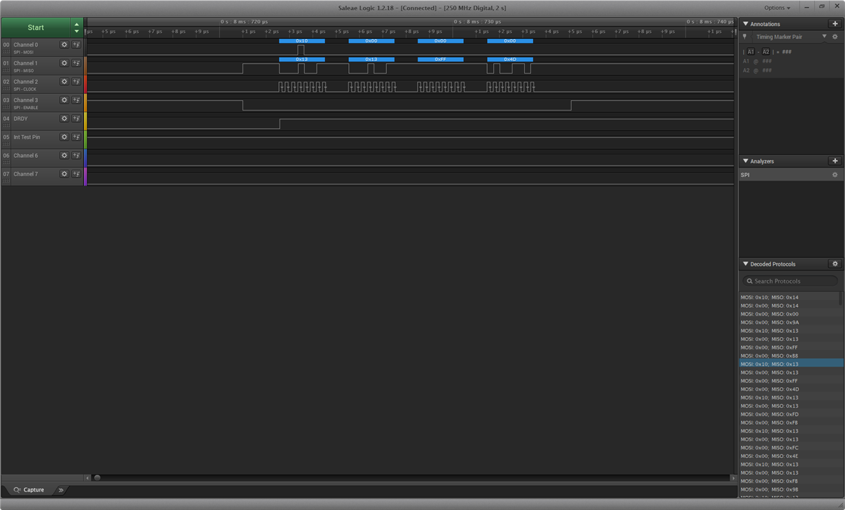
    Sorry, i didn't explain myself properly. Please see a screenshot below. Why is the second byte in some cases not the same as the first?

    Regards,

    Zoran

  • Hi Bob,

    I was trying to determine whether the SPI library i am using is somehow discarding the byte returned after i send the RDATA command. It is very strange because the Saleae data shows 4 bytes but when i discard the first byte, i receive incorrect data that jumps from negative to positive.

    Regards,

    Zoran

  • Hi Zoran,

    With the RDATA command there should only be 4 bytes of SCLK (1 byte command and 3 bytes of data) but I'm seeing 5 bytes.  I think this is due to this line:

    sData=ADS1220ReceiveByte();

    What this is doing is sending yet another byte of SCLKs.  What you really want to do is clear the RX buffer, especially if there is a FIFO.  It is not clear what happens in the functions SPI1_Write() and SPI1_Receive() functions.  It is possible that the buffer is cleared in these functions.  All you need to do in the end is make sure that the Saleae data matches with the results you are seeing from your code.

    Make sure that the Saleae settings in the analyzer are set appropriately.  These settings should match with the micro settings where CPOL = 0 and CPHA = 1.  If you fix these settings you will see that the 1st byte received will match the 2nd byte received in all cases.

    Best regards,

    Bob B

  • Hi Bob,

    Attached is the latest Saleae file with the settings corrected (thanks for that info). These results are with the line (sData=ADS1220ReceiveByte();) commented out. I do suspect that the buffer is cleared with the SPI1_Write() and SPI1_Receive() functions, but i was wondering if there is a way for me to confirm this? Can I convert the values i am receiving into a voltage and compare with the voltage across our sensor? Which equation would i use to do this?

    Regards,

    Zoran 

    250 MHz, 500 M Samples [1].rar

  • Hi Zoran,

    You don't need to back calculate anything, just look at the Saleae result and compare to the result in your code.  This data should match.  If it does you are good to go.

    Best regards,

    Bob B

  • Hi Bob,

    The system is working very well now thanks to your feedback. Your support has gone above and beyond my expectations.

    Regards,

    Zoran