This thread has been locked.

If you have a related question, please click the "Ask a related question" button in the top right corner. The newly created question will be automatically linked to this question.

ADS125H02EVM: - very confused

Part Number: ADS125H02EVM
Other Parts Discussed in Thread: ADS125H02

Hello E2E forum members,

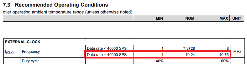
I'm having trouble getting the EVM to do anything that I think it should. It IS producing data. I'm trying to configure it to produce 40,000 sps sinc 5 filtered data. It is running on its internal clock. So that is 7.378 MHz +/- a couple percent Not 10.24MHz.  I THINK it should produce 28.8 sps when configured for 40Ksps at a clock freq of 7.37MHz. The MODE0 register is set to 0x83. This should satisfy the 10000 - 11111: 40 kSPS (fCLK = 10.24 MHz) . It is producing DRDY- at a 35.5Hz rate. The setting of 3 in bits 2:0 seems to select sinc4. No setting for sinc5. But maybe 40,000 setings produce sinc5 filtered data.

We want the sinc5 data with the first notch at the OWR of the filter. With an external clock of 2.048MHz we expect (and are told by TI) that this is a valid configuration.

Can anyone help?

Thanks

Terry Johnson

Consulting Engineer

  • One more piece of data: Running at (lower) rates intended for the internal clock at 7.3-ish MHz produce the correct output word rate, such as 100 sps..

  • Hi Terry,

    Welcome to the TI E2E Forums!

    I would highly recommend that you check out the ADS125H02 Design Calculator (Rev. A). This is an Excel Calculator that I put together to try to help clarify some of questions that you brought up. Nevertheless, I'll try my best to address your questions above...


    Terry Johnson said:
    I'm trying to configure it to produce 40,000 sps sinc 5 filtered data. It is running on its internal clock. So that is 7.378 MHz +/- a couple percent Not 10.24MHz. I THINK it should produce 28.8 [k]sps when configured for 40Ksps at a clock freq of 7.37MHz.

    The internal clock of the ADS125H02 will automatically scale up to 10.24 MHz when you select the 40 kSPS data rate, so you should be observing an output data rate of 40 kSPS  when using the internal oscillator.

    If however, you use an external oscillator of 7.3728 MHz and then select the 40 kSPS data rate, you are correct, the output data rate will be scaled by a factor of (7.3728 / 10) = 0.73728, so you'd observe an output data rate of 0.73728 * 40 kSPS, or 29.49 kSPS.


    Terry Johnson said:
    The MODE0 register is set to 0x83. This should satisfy the 10000 - 11111: 40 kSPS (fCLK = 10.24 MHz) . It is producing DRDY- at a 35.5Hz rate. The setting of 3 in bits 2:0 seems to select sinc4. No setting for sinc5. But maybe 40,000 setings produce sinc5 filtered data.

    This is something that I think also should be clarified in the datasheet...The DR selection is actually selecting which filter output to use. If you select any of the data rates equal to or greater than 14.4 kSPS, you'll get the SINC5 filter response. You are bypassing the SINCx and FIR filters, so it doesn't make any difference which filter mode you select with these data rates, you will be using the SINC5 filter. Likewise, if you select the FIR filter but program a data rate that is faster than 20 SPS, you'll get a SINC1 filter response.


    Terry Johnson said:
    We want the sinc5 data with the first notch at the OWR of the filter. With an external clock of 2.048MHz we expect (and are told by TI) that this is a valid configuration.

    This is a valid configuration...for the the 40 kSPS data rate you are allowed to use an external clock frequency between 1 MHz and 10.75 MHz:

    With a 2.048 MHz clock, the "40 kSPS data rate setting" will result in a data rate of 8 kSPS and a filter response like so:

    I hope that helps!

  • Hi Christopher,

    Thank you for the quick response. Some of you response is quoted here for my responses.

    "I would highly recommend that you check out the ADS125H02 Design Calculator (Rev. A). This is an Excel Calculator that I put together to try to help clarify some of questions that you brought up. Nevertheless, I'll try my best to address your questions above..."

    I WILL definitely get it.

    "The internal clock of the ADS125H02 will automatically scale up to 10.24 MHz when you select the 40 kSPS data rate, so you should be observing an output data rate of 40 kSPS  when using the internal oscillator."

    Maybe it is not adjusting accurately to 10.24 MHz? I get 35.5 Ksps when configured for 40K. This is actually the only unresolved issue. I will double check the settings with one of my colleagues.

    "If however, you use an external oscillator of 7.3728 MHz and then select the 40 kSPS data rate, you are correct, the output data rate will be scaled by a factor of (7.3728 / 10) = 0.73728, so you'd observe an output data rate of 0.73728 * 40 kSPS, or 29.49 kSPS."

    So a 2.048 MHz external clock should produce EXACTLY 8000 sps when configured for 40 Ksps. Since our clock will be locked to GPS, I say exactly.

    "This is something that I think also should be clarified in the datasheet...The DR selection is actually selecting which filter output to use. If you select any of the data rates equal to or greater than 14.4 kSPS, you'll get the SINC5 filter response. You are bypassing the SINCx and FIR filters, so it doesn't make any difference which filter mode you select with these data rates, you will be using the SINC5 filter. Likewise, if you select the FIR filter but program a data rate that is faster than 20 SPS, you'll get a SINC1 filter response"

    This confirms what I was assuming. Thanks.

    "This is a valid configuration...for the the 40 kSPS data rate you are allowed to use an external clock frequency between 1 MHz and 10.75 MHz:"

    Thanks again for double confirming this.

    I'm going to check this as resolved even though the 35.5 Ksps is a minor mystery.

  • Hi Terry,

    The internal 10.24 MHz oscillator should not be off by more than +/- 3.5%, so I'm not sure how you would get 35.5 kSPS. Are you observing this data rate by probing the /DRDY pin on an oscilloscope, or do you time the data rate in software?

    The data rate of the ADC is set by the master clock frequency, so you should get an output data rate pretty spot on with 8 kSPS. Maybe it's possible for some digital signal propagation times to have minute variations over temperature, but apart from that, the data rate will track with your external clock frequency. The times when I have observed any variations in the data rate, it was probably within the sampling rate and clock jitter of the logic analyzer.