This thread has been locked.

If you have a related question, please click the "Ask a related question" button in the top right corner. The newly created question will be automatically linked to this question.

ADS131A04EVM: ADS131A04

Part Number: ADS131A04EVM

Good day I am having some serious issue trying to hook up my MCU to the ADSEVM board.

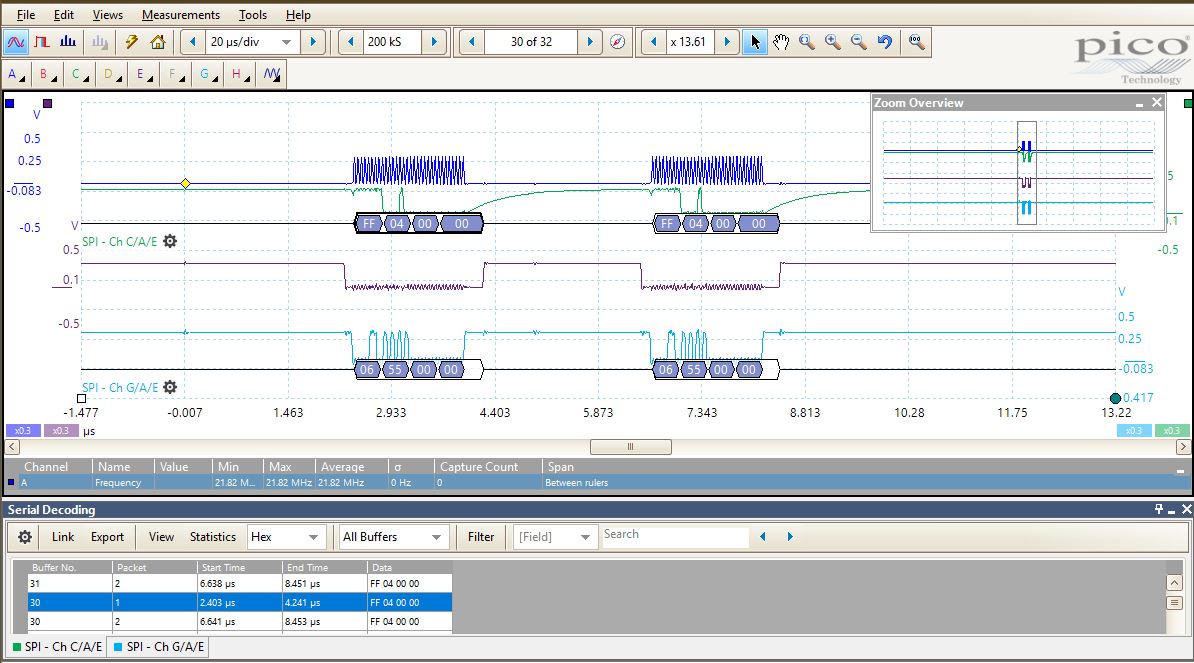
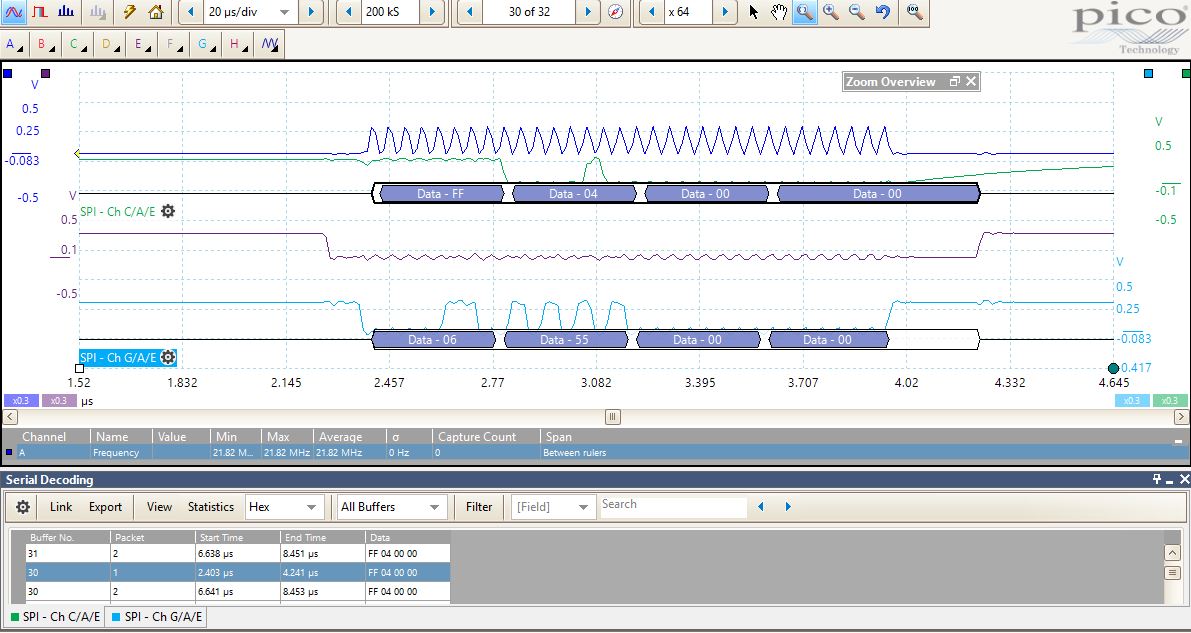
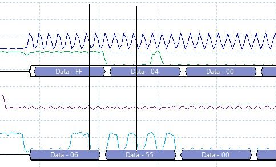
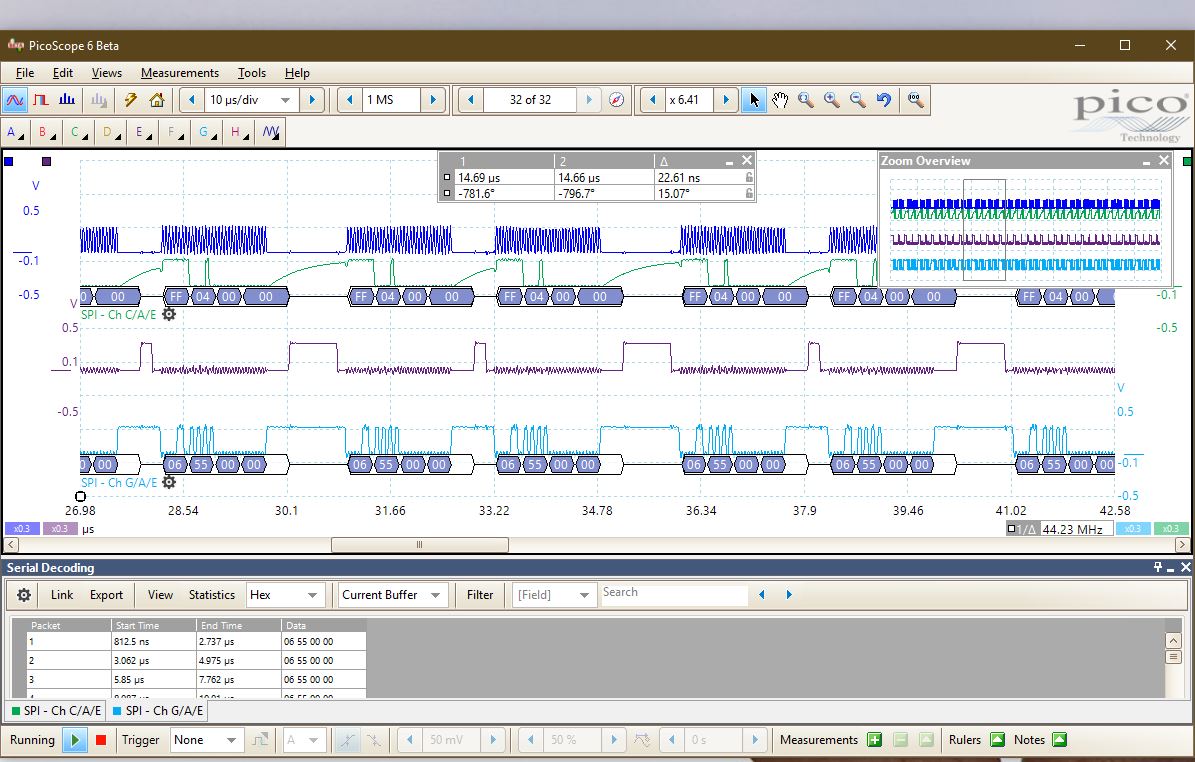
I am working on using ASync interrupt mode but my output doesnt change. it is just the 0xFF04 i see.


  • Charles,

    I'm sorry I didn't answer this earlier, but I've been out of the office.

    I haven't tried to use the EVM with an external controller, but I do know there are a couple of labeling mistakes on the EVM that might be a problem. In particular, the MISO and MOSI labels on the EVM. You can find some of the errata of this board in the E2E post below.

    I haven't tried to look at the communications that you've sent, but I would note that this device requires precise communication.

    Joseph Wu

  • How Precise exactly? Cause the datasheet has only minimum values and not mask i believe that as long as i am above the designated timings. we are okay to go .

  • Hi Charles,

    Could you provide more zoomed-in captures of the digital communication?  The current images show high-level behavior but we can't see the edges or timing behavior properly from this zoom level. I don't recommend using the "zoom" function on the scope but rather adjust the horizontal axis accordingly to capture the desired information at higher resolution.

  • Please i hope this is helpful, I am on the clock here.

  •  does this help also ? 

  • Hi Charles,

    Your clock signals look extremely frequency limited and look like saw-tooth waves at this point. You're not going to meet the basic logic levels or setup/hold times with digital clock signals that look like that.  Can you confirm that the waveforms don't look like this because of poor measurement techniques?

    I have a feeling they really look this way based on the long release of the green signal and you probably have a lot of capacitance on the digital lines either because of capacitors you've placed in the design or cabling capacitance.  Please remove the capacitance and see if things get better. 

  • The green signal is the SDO from the ADS131mo4 on board the EVm 

    still dont know why it looks like that.

    CS - Purple

    BLUE - Master SDO

    I have no capacitance on the line . I am just connecting jumpers to the EVM board 

  • THis is due to mismatch in the clock phase settings.

    Thanks 

  • Charles,


    I'm sorry I didn't get back to you earlier, but I was out of the office for most of last week.

    When I said last week that the device communication should precise, I meant that the device is expecting specific input, and giving specific responses. If the communication isn't receiving the proper commands or data, the command may not be executed. However, I don't think this is what is happening here.

    Can you check the version of SPI that you are using to send the ADC data to the device? Here's a blow up of one of the plots for your SPI communication. Here, you show a send of 06 55 to the device as an UNLOCK:


    However, your it looks like the falling edge of SCLK is coincident to the falling edge of the DIN line. The transmission should be that the data is clocked in at the falling edge of SCLK, so that the DIN should be transitioning at the rising edges of the SCLK. If you look at figure 1 of the datasheet on page 15, the communication is that the CPOL=0 and CPHA=1. It looks as if you have it set up as CPOL=0, and CPHA=0. Another way of saying this is that it looks like you have the microcontroller write set to SPI mode 0 and it should be set to SPI mode 1. You could confirm this with a higher bandwidth oscilloscope.

    One last point to mention was the slope that you see from the DOUT result. When you raise /CS, the DOUT line goes high impedance. Without any pull up, the DOUT may float to the supply. I think that's what you see here.


    Joseph Wu

  • Perfectly mentioned Joseph That was the only problem .

    It appears that the clock phase notation is different for manufacturers. Microchip's notation was different from that of TI.

    had to write a 0 instead of a one for clock phase.

    Thanks so much for your time. I am using a PIC32 just for reference purpose.  This is all due to the lack of standaradization of SPI.

  • Charles,

    I'm glad that my comments helped. If you have further questions, post again on the forum.

    Joseph Wu