This thread has been locked.

If you have a related question, please click the "Ask a related question" button in the top right corner. The newly created question will be automatically linked to this question.

ADS1231: Why the result I get from formula is different with the real voltage?

Part Number: ADS1231

Dear experts,

I am working with NXP™ LPC2138 Microcontroller and AD converter ads1231. Now I am facing with a problem: the input signal Vin is different with the value that I calculate with the formula from datasheet.

My setup:

Verfp: +3.3v

Vrefn: 0v(GND)

Voltage 3.3v is divided with a 20k and a 100ohm resistor. Range of thermistor is 0 to 100 ohm. Same divided resistor is connected with thermistor. So a comparative voltage is provided with the output of thermistor. They are connected to AINN and AINP respectively.

The formula proviede by datasheet is: (0.5VREF/128)/0x7fffff. That is: Vin=x*((0.5VREF/128)/0x7fffff). x is the data read from ads1231, VREF is 3.3v.

While I debuging application, I read a value 919001 from ads1231. Using the formula above, I get the result 1.4mV. But the real Voltage at AINN is 0.0175, Voltage at AINP is 0.0463. Difference of them is 0.0288. The difference with the result from formula is about 20 times! What wrong I do? Please tell me. Thank you!

Best regards

John

  • Hi John,

    The ADS1231 may not be the best device for your application.  As the gain is fixed to 128, you must not violate the input common-mode requirements.  The common-mode input range is given in the Electrical Characteristics table on page 3 of the ADS1231 datasheet under the ANALOG INPUTS parameter.  AINN and AINP must reside within the range of GND+1.5V and AVDD-1.5V.  For AVDD at 3.3 your input is restricted to 1.5V to 1.8V with respect to GND.

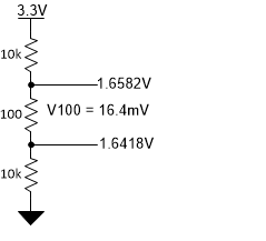
    If the resistor divider consisted of 10k - 100 - 10k you should be able to read across the 100 Ohm resistance properly.

    Best regards,

    Bob B

  • Hello, Mr. Bob,

    I am glad to see your reply. What you said is very important to me. You told me that ADS1231 may not be the best device for our application. But we design the circuit following the application example on page 16 of datasheet of ADS1231. I don't think the application example is wrong.

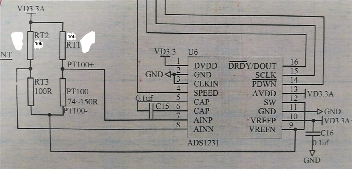
    Part of our sheet:

    I hope you could be kind to give me more advice. Thank you!

    Best regards.

    John

  • Hi John,

    Thanks for the drawing as this is slightly different than what I thought you were doing by your description.  If we look at just one leg using the original 20k Ohm resistor in series with 100, then by Ohm's Law we can calculate the voltage at AINN. VRT3 = VD3.3A (RT2/(RT2+RT3).  VRT3 is only 16.4mV above GND.  VRT3 is connected to AINN, and AINN must be greater than 1.5V above GND as I discussed in my previous post.  So this input is not within the acceptable range.  My suggestion was to alter the voltage divider so that instead of using a single 20k resistor you use two 10k resistors.

    Rearranging the values does not change the voltage drop across the 100 Ohm resistor.  For the other divider leg you would need to do the same change.

    Figure 24 on page 16 of the ADS1231 datasheet shows a bridge circuit for a load cell.  This configuration differs from the one you are using in that the values of the bridge elements would be equal in a no-load condition making AINN and AINP 1/2 of the excitation supply.  Your original circuit would work in a similar way if the 20k resistors are changed to 100 Ohms.  However, you will have a lot of self-heating of the temperature element as the current through the sensor would increase substantially.

    There are some other devices that could be used for temperature measurement using alternate schemes.  I would suggest taking a look at the following RTD measurement guide:

    http://www.ti.com/lit/an/sbaa275/sbaa275.pdf

    Best regards,

    Bob B

  • Thank you, Mr. Bob! My problem had been resolved perfectly!

    Best regards!

    John