This thread has been locked.

If you have a related question, please click the "Ask a related question" button in the top right corner. The newly created question will be automatically linked to this question.

ADS4222: ADS4222EVM input questions.

Part Number: ADS4222

Dear team,

I have three questions about using ADS4222EVM, could you please help on those questions? Thank you.

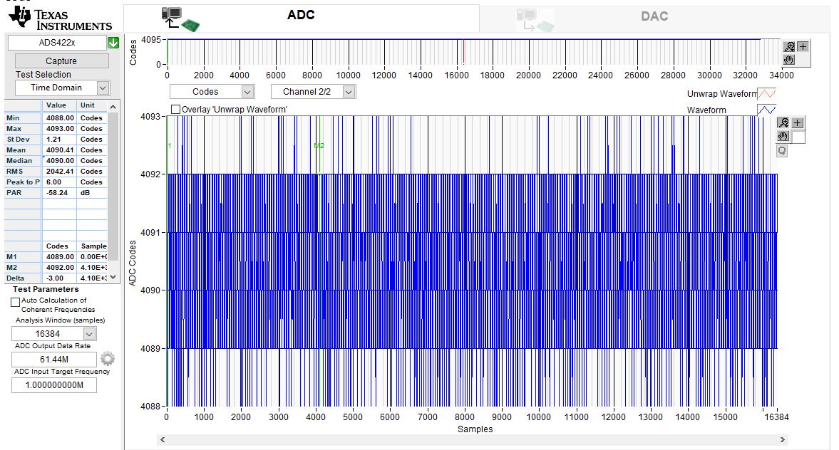
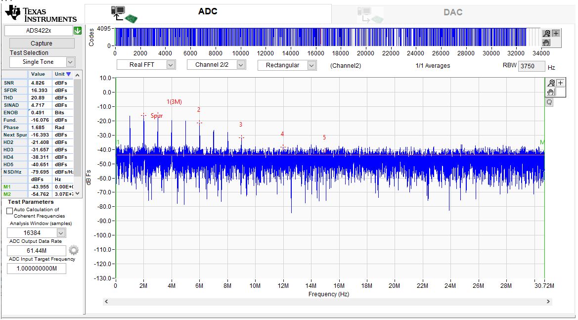
1. I used ADS4222EVM+ TWS1405EVM and used HSDC pro to capture input signal.

When I feed:

Input Amp:-50dBm; Freq:1MHz at J6

Clock source: 61.44MHz at J19

I can get good FFT, but the code has some peak as the following picture. May I know the reason?
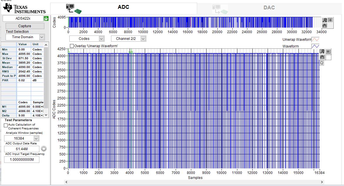
2. When I feed:

Input Amp:-40dBm; Freq:1MHz at J6

Clock source: 61.44MHz at J19

The FFT is really bad, and it seem input signal is saturated. But I saw the input spec of ADS4222 at datasheet can feed 2Vpp input signal. Why does ADC input saturate at only -40dBm?

3. How to revise the EVM if I would like to input 1kHz?

Because 1kHz input will be filter out by WBC1-1.

I think I could revise the following settings at EVM to feed 1kHz. Please let me if this is correct or any missing.

  • Short T1 pin1 to pin6 and pin4 to pin3.
  • DNI R119 and R123.
  • Put 0hms at R120 and R129.
  • Put 50ohms at R19 and R42

Regards,

Polly Chung

  • Polly,

    We are looking into this.

    Regards,

    Jim

  • Polly,

    In the ADS4222 GUI, you must change the Data Format to Offset Bin. By default the GUI sets this to 2's Comp.

    Regards,

    Jim

  • Polly,

    If you plan on using the on-board amplifier you will have to do all of the steps you mentions plus add 0 Ohm resistors for R131 and R132 and remove R143 and R141. You will also have to move the shunt on JP4 from pins 2-3 to 1-2 to power up the amplifier.

    Regards,

    Jim 

  • Dear Jim,

    Thanks for your reply. I still have some questions, could you please help check them? Thanks again.

    1. Do you mean the reason why input signal saturated is because of the wrong data format setting in GUI?

    2. What is our test setup for INL spec of ADS4222 (datasheet P17)?

    3. Could we use on amplifier to test DC linearity?

    Regards,

    Polly

  • Polly,

    For #1, yes.

    For #2, I do not know the answer to this.

    For #3, yes, but a high resolution DAC might be a better choice.

    Regards,

    Jim

  • Dear Jim,

    Thanks for your help. My customer revised ADS4222 EVM circuits as we suggested in the following lists to measure the ramp source (frequency 100KHz and amplitude +5dBm, offset 0VDC). But they can not get desired waveform from ADC. And we have tried to input DC, but we found it was filtered out by C11. Looking into EVM schematics, we suspect that the input signal no matter DC or 100kHz will be filter out by C11, C13, C51. You could see the waveforms at attached ppt for more details.

    Because my customer's application need to measure the DC and lower frequency input signal, could you please let us know what else we should revise at EVM schematics to meet my customer requirements? Thank you.

    20190906_ADS4222 lower frequency and DC issue.pdf

    --------------------------------------------------------------------------

    1. Short T1 pin1 to pin6 and pin4 to pin3.
    2. DNI R119 and R123.
    3. Put 0hms at R120 and R129.
    4. Put 50ohms at R19 and R42
    5. Add 0 Ohm resistors for R131 and R132
    6. Remove R143 and R141
    7. Move the shunt on JP4 from pins 2-3 to 1-2 to power up the amplifier

    --------------------------------------------------------------------------

    Best Regards,

    Polly Chung

  • Polly,

    The customer also needs to replace C13 and C66 with 0 Ohm resistors. It appears they missed this. The signal is still AC coupled otherwise. 

    Regards,

    Jim