This thread has been locked.

If you have a related question, please click the "Ask a related question" button in the top right corner. The newly created question will be automatically linked to this question.

ADS1292R: No output after power up

Part Number: ADS1292R

Hi Team,

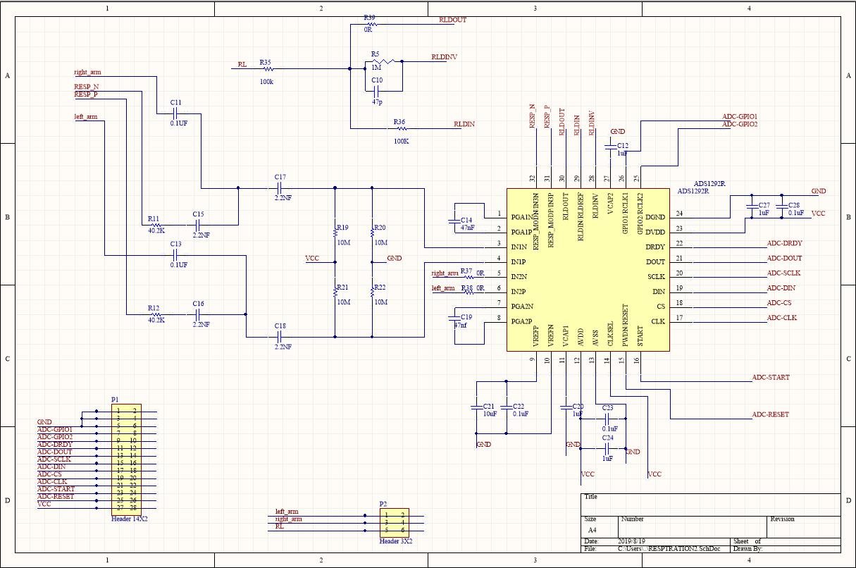
Customer is using ADS1292R as below schematic, but they find no output after use 3.3V LDO power supply.

Their is a low resistor path between VCC and GND after power up and the total current is 0.27A. But if customer depopulated the ADS1292R, then no low resistor path would be detected. So customer want us to help check whether the schematic is correct?

Any comments are welcomed! Thank you!

Marc

  • Hi Marc,

    There's not a lot to go off of here, at first glance I don't see anything wrong with the schematic. 

    Is this an issue with a single board or across all created PCBs? 

    If the device is replaced with a new device, does the problem persist? 

    Any visible damage (or burnt smell) to the device? 

  • Hi Marc,

    Thank you for your post.

    Can you have the customer measure the impedance between VCC and GND without applying power? You cannot always get an accurate impedance measurement when current is flowing between the two probe points.

    There's nothing obviously wrong with the schematic that would indicate a power-up issue. What is the VCC supply voltage and source?

    Best regards,