This thread has been locked.

If you have a related question, please click the "Ask a related question" button in the top right corner. The newly created question will be automatically linked to this question.

AMC1305M25: Layout and GND connection

Part Number: AMC1305M25

I'm curious about the two questions here.

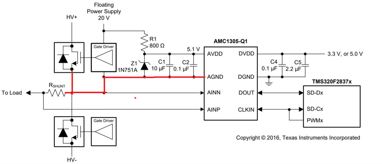
1. Why The AGND pin of the AMC1305M25 needs to connect to the one of the R shunt terminal? The floating power supply needs to connect to AVDD & AGND pin of AMC device for bias power, correct? Or other good reason?

2. Regarding to the layout with delta-sigma ADC, in general the IGBT module could be far away from the AMC1305 device and R shunt depends on different form factor. If so, how to do the layout optimization between the AGND of the AMC1305, Grounding of the Gate driver, IGBT's GND and Rshunt? Which GND connections should be as close as possible? 

  • Hi Brian,

    The AGND of the AMC device typically connects to one of the RSHUNT terminals as well as the negative input so that the positive input can swing to +/-250mV. The floating power supply must be referenced to this GND as well so that the system drifts together and the device ratings such as acceptable power supply range and input common-mode limitations are not violated. 

    Placing the shunt close to the device and making sure that the traces from the shunt to the inputs of the device are matching in length is a good idea. The rest of it depends on the system and what is possible. There are many things to consider such as what other components are present, how many layers is the board, are GND planes or traces being used, etc. There's a lot of theory on GND planes and it's tough to come up with one "true" solution.

  • Hi Brian,

    As Alex mentioned, the input common mode range of the AMC1305 is limited to the AVDD supply voltage, so typically the AINN (or AINP) node is referenced back to the AGND pin to ensure you do not exceed the Vcm limitations of the device.

    Ideally the AGND is connected nearby the shunt, rather than trough the bond wires and the body of the IGBT module.  That type of connection can add some parasitic impedance/inductance and potentially impact the measurement results.  I'll try to send over some detail from a TIPD where the SEM team did some characterization on the impact of direct connection versus through the IGBT body.