This thread has been locked.

If you have a related question, please click the "Ask a related question" button in the top right corner. The newly created question will be automatically linked to this question.

LMP90080-Q1: LMP90080-Q1 application problem

Part Number: LMP90080-Q1

hi,

CTM has used LMP90080-Q1 in system. But they have met some application problem. the details as follow.

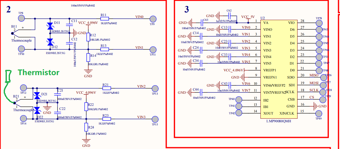
A The Part of Schematic

B Problem description

1 SPI communication is OK, and the configuration gain is also good. When reading data, the channel is misplaced. 

For example, the input of CH0 is displayed in CH1, and the input of CH1 is displayed in CH2. 

2 The description of several sampling modes in datasheet is not very detailed. The situation is the same as that described in description1 when we change the sampling mode.  

3 Please provide the main registers needed to be configured and the configuration examples.  

The specific problems are as follows:

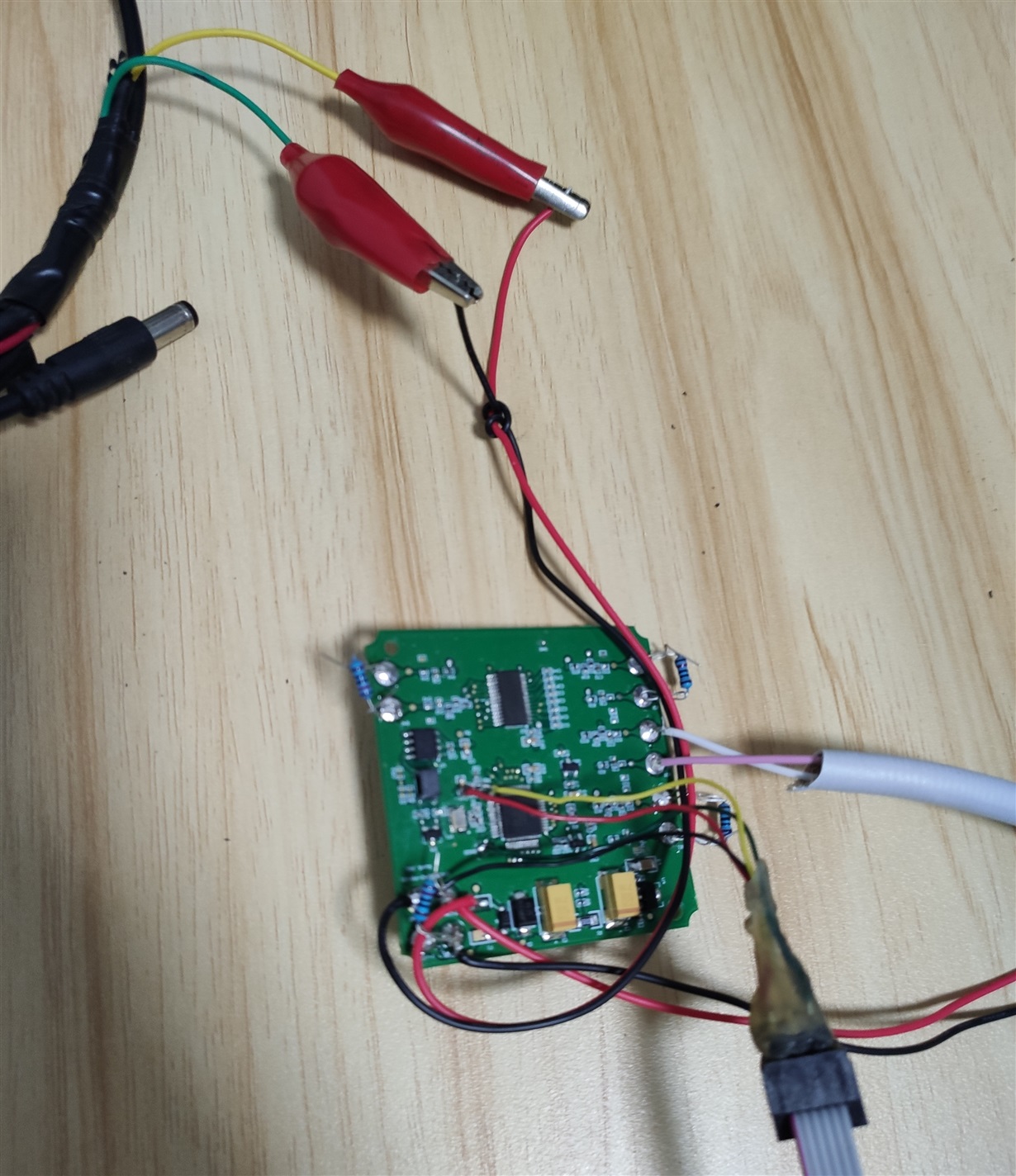
1)      The test overview and configuration picture.

         CH1 connected to thermistor

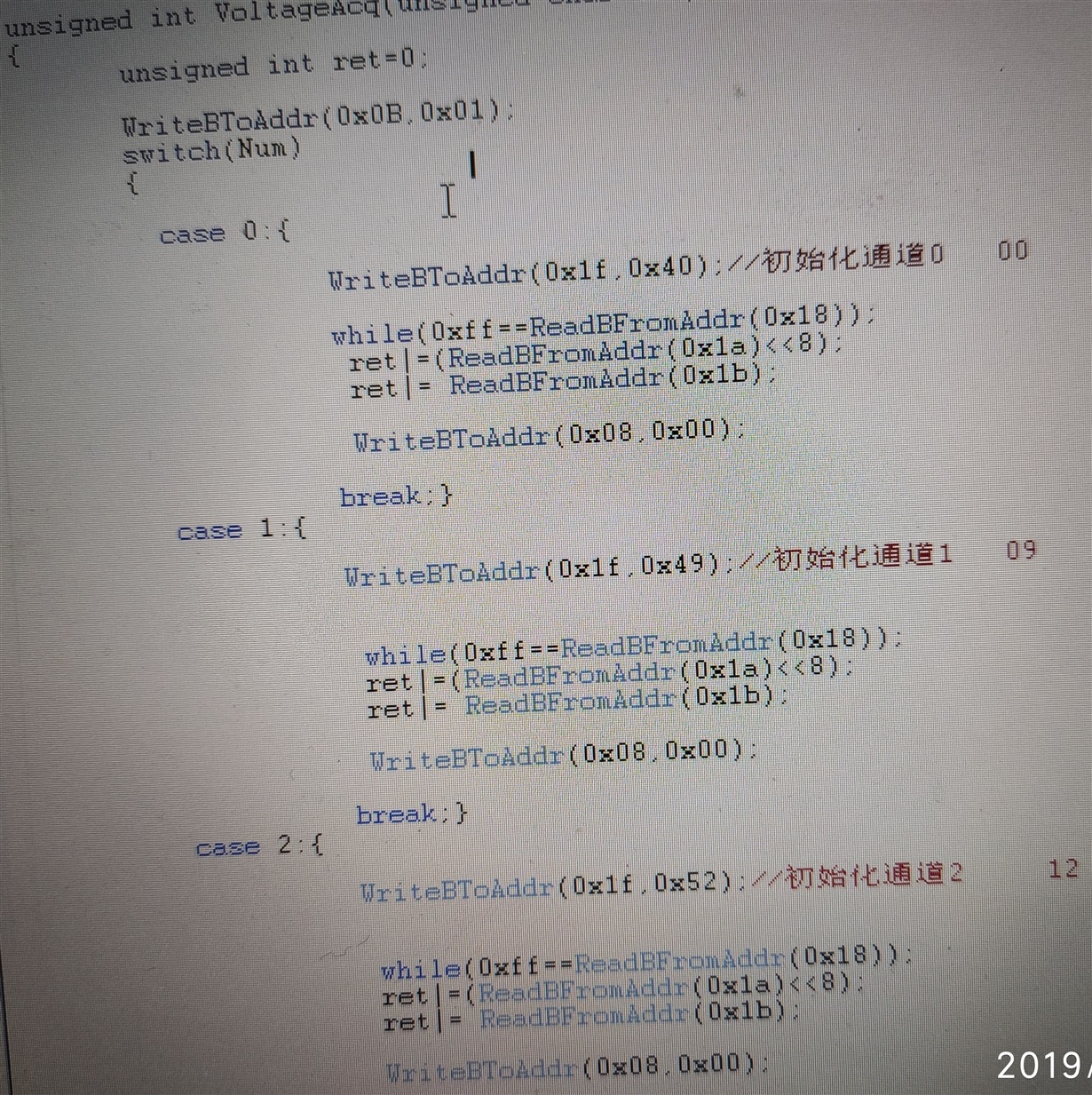
Initialization configuration

Configuration of each channel

CH1 connected to thermistor

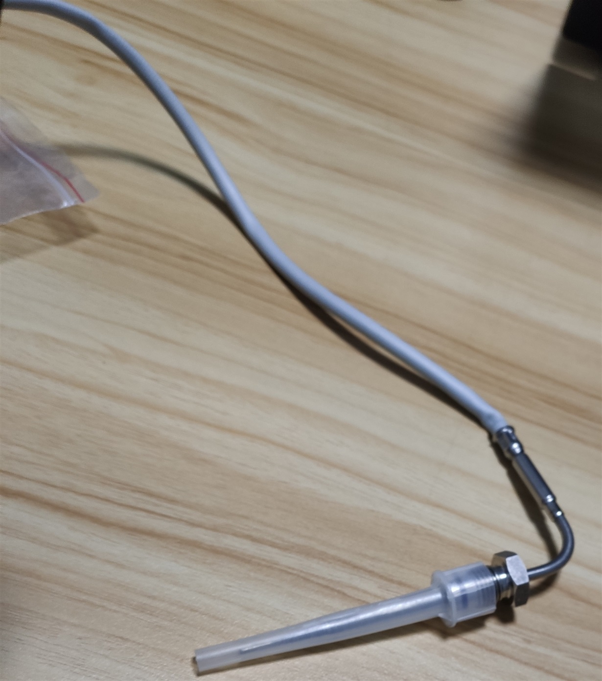
2)      Configure as 4CH test mode, the test result is as shown in the figure, N-type thermistor is connected to CH1, but the test data is shown in CH2

3)      Configure it as a single channel test mode, Remove the other three channels. There is no problem with the test data. The value is shown in CH1.

Touch the thermistor by hand, and the data will be displayed in CH1 correctly.

May I get your swift support? thanks.

BRs

  • Hi Kun,

    Do you see this behavior on all channels?

    I.E. Ch1 shows up as Ch2, Ch2 shows up as Ch3, Ch3 shows up as Ch4, Ch4 shows up as Ch1?

    Can you share the output bit stream that you're using to identify which channel is being used? 

    It looks to me like the channel MUX settings are in the default position.

    I think it may be something to do with how address 0x1F is being written to, CH_SCAN. Can you help me understand what is the purpose of the case statements from the picture? 

    Try writing 0x18 to register 0x1F in order to set LAST_CH to CH3 and FIRST_CH to CH0.

  • hi,

    I.E. Ch1 shows up as Ch2, Ch2 shows up as Ch3, Ch3 shows up as Ch4, Ch4 shows up as Ch1?====> yes

    Can you share the output bit stream that you're using to identify which channel is being used? ===> I have communicated with software engineer to get it.

    It looks to me like the channel MUX settings are in the default position.I think it may be something to do with how address 0x1F is being written to, CH_SCAN. Can you help me understand what is the purpose of the case statements from the picture? Try writing 0x18 to register 0x1F in order to set LAST_CH to CH3 and FIRST_CH to CH0.===> I will try it.