This thread has been locked.

If you have a related question, please click the "Ask a related question" button in the top right corner. The newly created question will be automatically linked to this question.

ADS131E08S: Output wraps between 32768 to -32768

Part Number: ADS131E08S
Other Parts Discussed in Thread: ADS131E08

Hello Team,

Currently, we are using the ADS131e08 chip, for measuring the resistance. ADS131e08s chip is connected to a microcontroller, communicate with SPI protocol. ADS131e08s acts as a slave and microcontroller act as a master. ADS131e08s and microcontroller communicate with each other with SPI protocol.
Using the RDATAC command, we are able to get the readings from the ADS chip, but the output is getting wrapped at a positive value of 32768(16 bit) and the negative value of -32768.


By default in the CONFIG1 register, DR[2:0] bits is set to 4, which should result in 24-bit output, but it always results in the 16-bit output. We also tried to change DR[2:0] bits in CONFIG1 register, but it didn't change the result. We are able to measure the correct data rate, for corresponding DR[2:0] bits value.

Could someone please tell, how it needs to be corrected, so that output would be 24 bit.

I have also attached a  
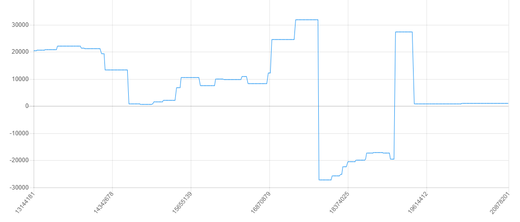
screenshot of wrapping for your reference.

Thanks in advance,
Best regards,
Chetan

  • Chetan,


    There are a few things that could be a problem. However, I'll suggest a few things to look at to try and debug this.

    First, what is the DR setting that you using? You mention that you have it set, but you don't mention what value you use. Have you tried reading the register back to ensure that you get back the value you expect? If you do try this, I would start by trying to read the default value just to make sure that you get an expected value. Then try writing and reading back the register.

    I would also start by measuring something simple first. Start by shorting the inputs to something near mid-supply and take a large series of measurements. This would give you results near zero, with some noise. You can collect this raw data in hex and put it in an excel file to post back here. If you want, you can post an excel file of the results from the plot in your last post.

    Then I would use a set resistance for a measurement so that you get a value that is consistent. Record the voltage across the input, the reference value, and the gain. Again, this would be a constant result, so the input voltage shouldn't change much with time (except for noise) I would also collect this data and put it in an excel file. I'll probably need an explanation on how this resistance measurement is set up.

    Another thing to check is the SPI communications. You'll need a logic analyzer or oscilloscope to check the DIN, DOUT, /CS, SCLK, and /DRDY if possible. SPI settings are CPOL = 0 and CPHA = 1.

    One last thing to check is the relationship between /DRDY and the device read. This is important if you are using the read data continuous mode (which is the default mode). In this mode /DRDY falls and SCLKs are used to clock out the data. The important thing to note is that the SCLKs should clock out the data before the next completion of conversions (next /DRDY falling edge). If you are clocking out data, and the /DRDY falls during the read, the data will be corrupted. The DOUT register updates with new conversion, and doesn't wait for the readout to complete.

    Look over these comments and check out the operation in your system. We can review the results when you post back.


    Joseph Wu

  • Chetan,

    I haven't heard from you for a while, and I wanted to check on your read problem. In my last post, I gave a few things to look at, including SPI setup problems and a few tests to run to check the results.

    I'll close this thread for now. If you continue to have problems, post back and we can continue to work on this issue.

    Joseph Wu