This thread has been locked.

If you have a related question, please click the "Ask a related question" button in the top right corner. The newly created question will be automatically linked to this question.

ADS131E08: ADS131E08 does not power up

Part Number: ADS131E08

Hi,

I'm using an ADS131E08 but I can make it to power up.

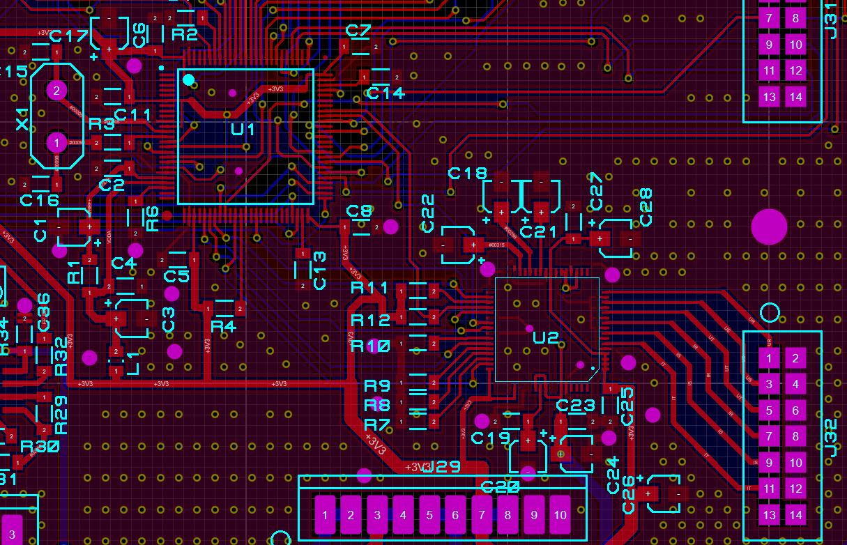
My application circuit is as follows:

SPI and RST_AD are also connected to microcontrollers, but they are High-Z right now.

When I measure VCAP1, it is 0.15 V. What can be happening?

Thanks!

  • Sorry, but I didn't receive any response. Can someone help me? Thanks!

  • Pablo,


    I've looked through the schematic, and I don't see anything wrong in the pin connections. However there are a few things to check. First, I would make sure that the START command has been issued. With that, you should see a /DRDY indication for the conversions.

    I would also check to see that the /RESET and /PDWN are both high. As active low, they go into reset or power-down when they go low. Check to see that the master clock is going CLK.

    I would also look at the physical connections on your board. Make sure that there aren't any solder bridges or unexpected shorts from pin to pin. Can you show a photo of the device on the board and a layout?


    Joseph Wu

  • Hi Joseph!

    Thanks for your response.

    I will generate the images and let you know.

    However, I've been analyzing the application note of the ADS131E08 and I noticed that all the capacitors connected to VCAP pins are not polarized. I used electrolytic polarized capacitors. Can this make the AD to not work?

    Thanks,

    Pablo

  • Joseph,

    Here is the layout of my board. As i mentioned before, I used electrolytic capacitors, so they are polarized. Can it be a problem?

    Thanks!

  • Pablo,


    I'm sorry I didn't get back to you yesterday, but I was out of the office.

    I've had a chance to look through the layout and the schematic and I still don't see what the problem could be. I've checked the layout to the pins of the device and I don't see where it may be wrong. Can you also post a picture of the device mounted on the board? There might be a view of some problem in the physical connections, like a solder bridge or a cold solder joint connection.

    Have you tried applying any digital signals to see if the device responds in any way? You might get some /DRDY response with just applying power. Have you used a multimeter to measure the digital voltages directly to make sure that the /RESET and /PDWN pins are high (not relying on the pull up resistances on the board). I would also verify all voltages on the pins just to make sure they are all where they should be. Are you able to measure currents from the supplies as well?

    Again, I don't see anything that's specifically wrong. I would guess that this is some sort of physical problem, but I can't verify all of your connections.


    Joseph Wu

  • Pablo,

    I haven't heard from you for a while so I thought I'd check on you. As I mentioned in the last post, I didn't see anything specifically wrong in your schematic and layout, but there could be some other problem with the build and I gave a few things to check.

    I'll close this thread for now, but if you continue to have problems, post back and we can continue to look over your schematic and system.

    Joseph Wu