This thread has been locked.

If you have a related question, please click the "Ask a related question" button in the top right corner. The newly created question will be automatically linked to this question.

ADS4222: Data capture voltage level

Part Number: ADS4222

Hi,

Currently Testing the ADS4222EVM with TSW1400EVM.

Providing the Input channel A with 300mVpp sinewave with 5MHZ and clock signal sine wave 1Vpp 64MHZ.

Images as below.

The question is How to see the voltage level proper sinewave output as given in the input.

In captured image it is square swing from -1 to +1 , it is not 300mVpp . please let me know what i am missing here and to be corrected.

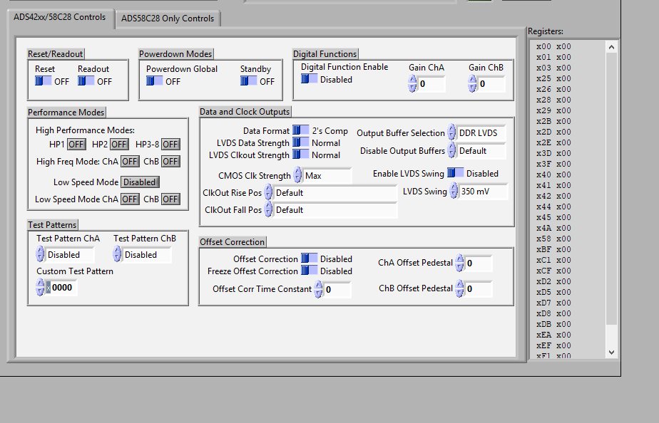
Currently using Default LVDS output from EVM to TSW1400EVM

  • Chiranjeev,

    The ADC output format needs to be set to Offset Binary. It appears you have this set to 2's Comp.

    It appears you are saturating the ADC. Please measure the voltage at the input pins of the ADC. I think you will find these are much larger than 300mvP-P. On the EVM it takes an input of ~ 2.6V P-P to get 2V P-P at the ADC inputs.

    Regards,

    Jim

  • Jim,

    Thank you for quick response.

    As suggested After changing to Offset binary below are the captures, but results not able to analyse.

    when input is 200mV P-P at 1MHz, the capture showing around 80mV P-P

    (when i measure the input at C11 it is showing 100mV P-P in Scope, without connecting to it directly measuring from signal generator the input is 200mV P-P)Also I see the transformer is 1:1,  the question is why after connecting to transformer it is reducing to half from 200mV P-P to  100mV P-P?  Attached the captures in pdf.

    Similarly, When input is 600mV P-P, at 1MHz  the Capture showing 230mV P-P

    when input is 400mV P-P, at 5MHZ, the capture showing 160mV P-P

    I checked with Channel 2 , the behavior is same.


    Please assist what to be done for correcting the same

    Also attaching the single Tone FFT- seems like Noise is high.

    Captures_1.pdf

  • Chiranjeev,

    There may be something wrong with your signal generator. With 200mV in, I get 160mV P-P out. With 600mV in, I get 550mV P-P out. C11 is not a good point to measure as the termination is not proper here. You need to measure at the ADC input with your source connected.

    Do you see this problem on both channels?

    Your FFT should look like the one attached. 

    Regards,

    Jim

    5MHz input tone, 600mV at source output.pptx

  • Jim,

    Thanks for sharing , I provided the same 600mV ,5MHZ as in your PPT and am Able to see approx same behavior (attached)

    Could you please share the same input for  Time domain with X time and Y voltage . ( I have attached mine with both single tone and Time domain captures in which I see around 480mV PP for 600mV pp in time domain.).

    captures2.pdf

  • Jim,

     any update for above,Awaiting for your response.

    Thanks

  • Chiranjeev,

    I was on vacation last week. Here is the data you requested.

    Jim

    5MHz input tone 480mv 600mV.pptx

  • Thanks Jim,

    I am having little drop due to the cable or signal Generator not sure, anyway i will check on this.hence closing this thread.

    also i wanted to measure an pulse signal which is actual requirement using ADS4222 and  i will update in another thread if i come across any issues for the same.