This thread has been locked.

If you have a related question, please click the "Ask a related question" button in the top right corner. The newly created question will be automatically linked to this question.

ADS1243: Can't get it to work

Part Number: ADS1243
Other Parts Discussed in Thread: MSC1210

Hello,

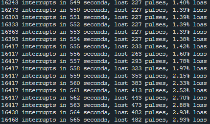
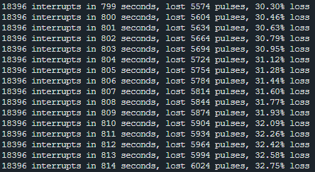
I have a problem with the ADC. I simply can't get it to send me DRDY pulses. When I read from registers I also get the same results (usually 255 or 0 from all registers)

This is my wiring:

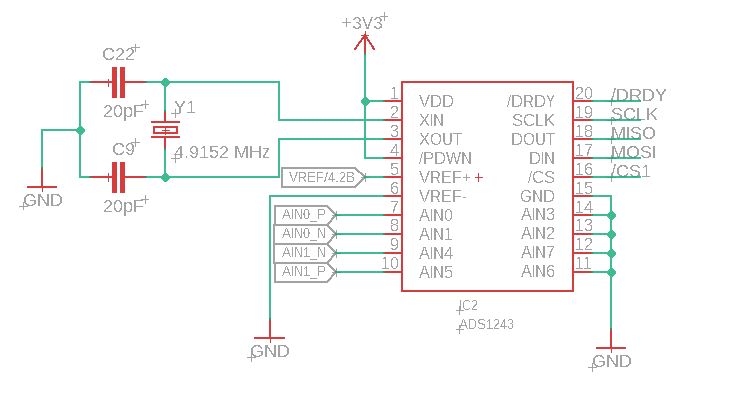
I think that the wiring is correct and I am not missing anything. Maybe only a decoupling capacitor at VDD.

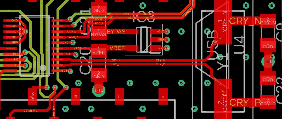
This is the part of the board with crystal:

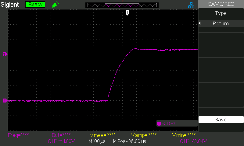
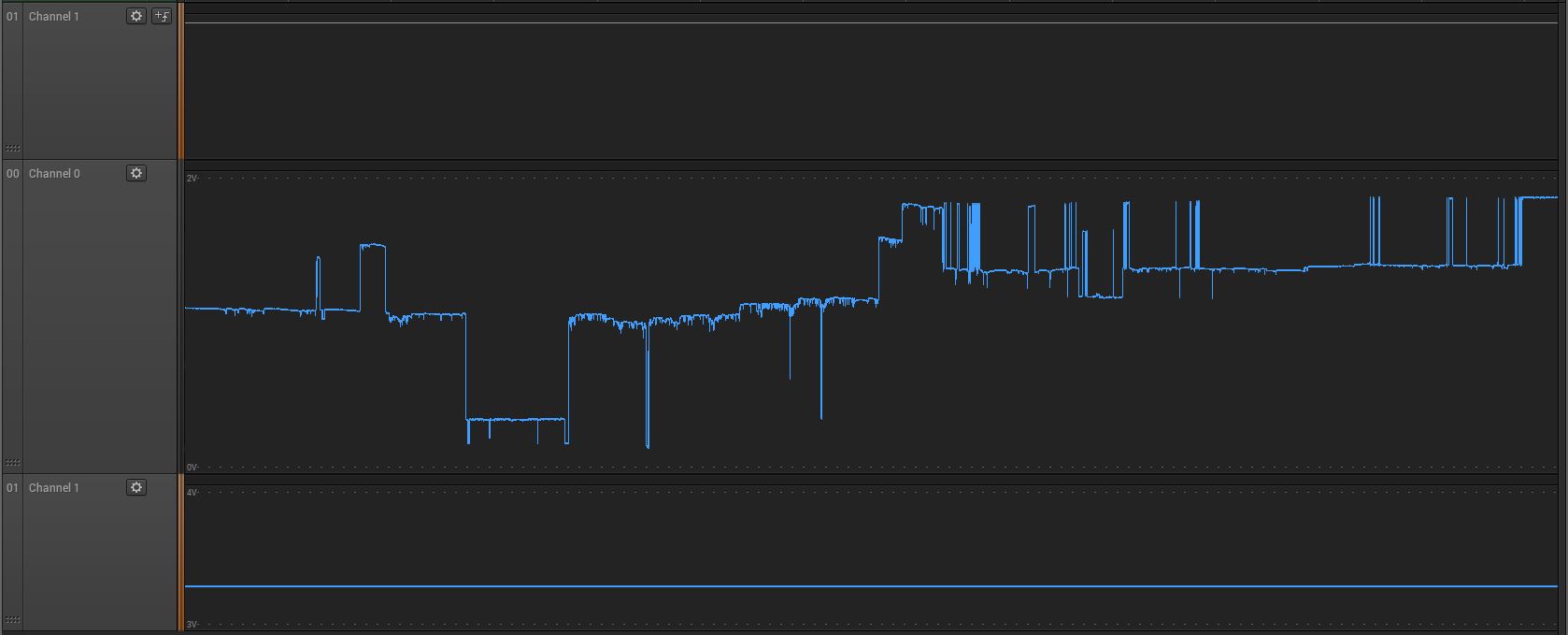
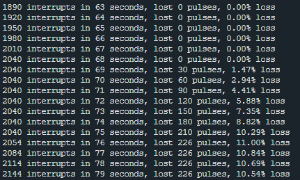
When I turn on the board the DRDY is high and it gets low after a few seconds and it won't get high anymore or give a pulse.

The supply voltage is 3.3V as you see. I use a LDO regulator from 3.5V to 3.3V.

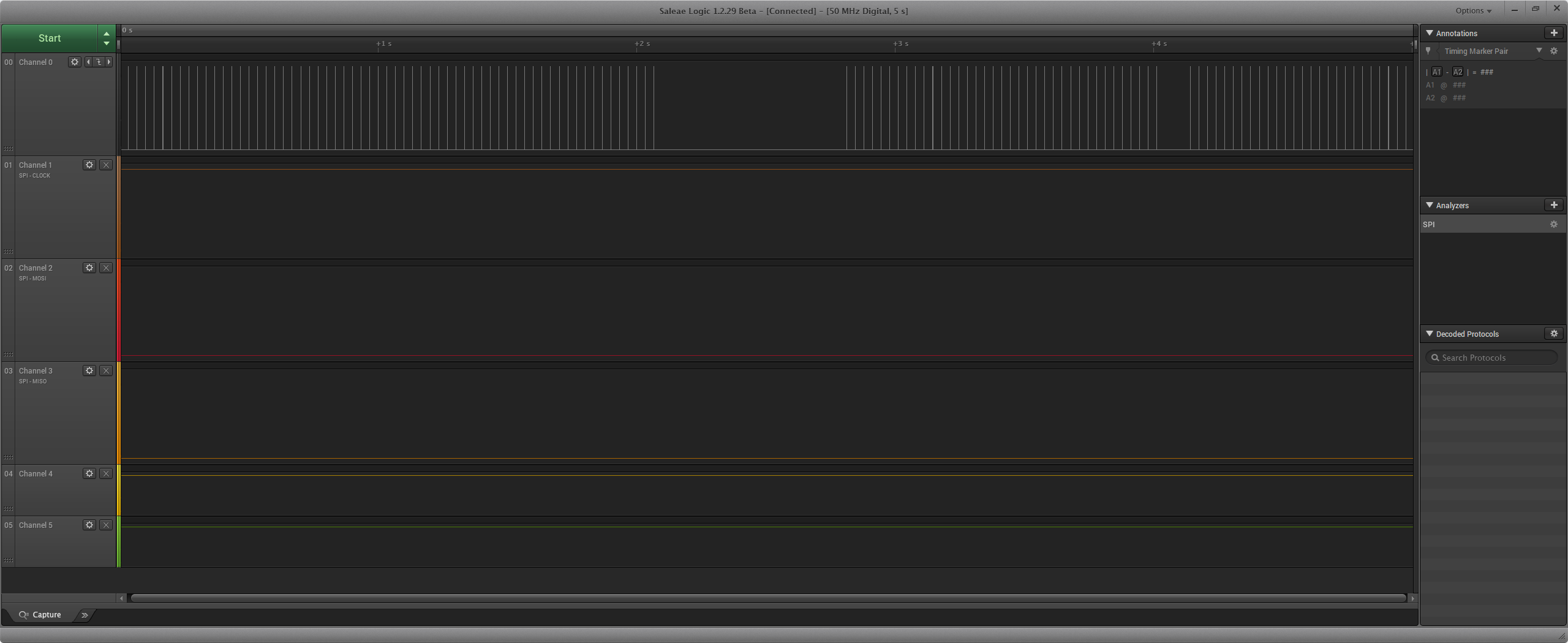
The control board is NUCLEO-L432KC and the function to read registers is:

CS1 = 0;
char pp[2] = {0x10,0x0F};
char rd[16];
mspi.write(pp, 2, 0, 0);
wait_us(500);
mspi.write(0, 0, rd, 16);
CS1 = 1;

The rd[0] to rd[15] is then Feedback: 255, 255, 255, 255, 255, 255, 255, 255, 255, 255, 255, 255, 255, 255, 255, 255

  • Hi Niko,

    Welcome to the E2E forum!  It is always a best practice to have bypass caps near the supply entry point to the ADS1243.  However, I doubt that this is your issue.  Most likely the crystal is not starting up properly.  You can verify this with an oscilloscope.  Based on the layout and the cap loading you are showing in the schematic I think the capacitance is too high in value.  I would try removing the caps entirely or reduce the caps to 10pF to see if the device responds correctly.

    Best regards,

    Bob B

  • Hi Niko,

    Improper device ID is often caused by an improper power-up routine. The device can start up accurately with 1V/10ms, but you may want to verify how quickly the device is powering up without a capacitor. 

    Is your reference voltage 4.2V? If so, this is well outside of the range for Vref and would explain why you're seeing full-scale results from the ID register. 

  • Hello Alex, 

    Thank you for the reply. I check the supply with the oscilloscope while power on. and It is way faster than 1V/10ms, in fact, it powers up to 3.3V in less than 200us. 

    No, The reference is 2.5V, The 4.2 just means the reference to list 4, column 2 in the schematics. Here is the design of the power supply:

  • Hello Bob!

    Thank you for the warm welcome!

    I'll add some bypass capacitors in the updated board, but first I have to get this ADC going.

    I never had such problems with crystals yet or start-up of it yet, so I'm new at this.

    How do I measure the crystal with an oscilloscope? Do I connect it directly to the crystal? 

    I think that it's best I send the components I used.

    So, the ADS1243, crystal, 20pF, LDO3.3V, LDO2.5V

    These are the pictures of the crystal. The last picture is without capacitors (basically the same result).

    The voltage is pretty much stable between 3.161V and 3.110V.

    Anything else I could try?  I would very much appreciate it!

  • Hi Niko,

    Something is definitely wrong with the crystal and I'm not surprised that the ADC is not starting up with this type of clocking signal. 

    The link for the crystal doesn't work for me, can you repost it? 

    I would recommend double-checking the crystal's datasheet to see if something is missing and/or wrong to cause this type of output.

    Replacing the crystal may be necessary if it's been damaged.  

  • Hello Alexander!

    Oh, I'm sorry, The hyperlinks were not working correctly. I fixed them now and they should be working perfectly now!

    The datasheet seems to be pretty empty, more or less it is only about footprint and temperatures.

    I had the same behaviour with the board before, that is why I made a complete reconstruction. I even tried with only all the basic components on the previous board (ADS1243, crystal and that's it). 

    Is there any other trick I could try?

    Here is another shot with the analyser.

    Channel 1 is DRDY and channel 0 is the Xout of the ads1243. It seems that the ADS1243 does not give the correct output. I must say that in total this is probably my 6th ADS1243 (5 on previous, 1 on this board) and I could not get any of them working. Tried with different crystals on the previous board.

  • Hi Niko,

    It is a little tricky checking the oscillator with the oscilloscope as the scope probes add capacitance.  Try looking at just the XOUT pin with the scope.  You should see a waveform that is around 200mVpp or more.  The frequency should match closely to the crystal frequency you are using.  Adjust the scope appropriately to view the waveform.  You may need to set the scope to AC coupled.

    If the scope probes are adding too much capacitance, you may have to experiment with the cap loading using different cap values and see if DRDY is toggling with the scope.  This is kind of painful as you need to use a variety of caps to tune the oscillator.  Sometimes using just one cap instead of the 2 will get it to oscillate.  Sometimes adding a resistor helps. I've included an old application note that is specific to the MSC1210 family, but many of the principals apply.

    2480.SBAA123_Using_Crystal_Oscillators_with_MSC12xx.pdf

    Another possibility is the crystal is damaged.  The crystal is sensitive if shocked by dropping or extensive soldering.  An alternative to the crystal is to use a clock source from a micro or an external oscillator into the XIN pin.

    Best regards,

    Bob B

  • Hi Bob,

    As I feared regarding the oscilloscope. I don't think that the crystal was physically nor thermally abused :) 

    Ok, the setup I tested now was:

    Crystal without load capacitors, connected oscilloscope probe to Xout, where I set the probe to x10 ( on the probe characteristic it says that 1X has around 100pF capacitance whereas x10 has 18-22pF. The result seems pretty much the same as before. I also tried with the probe on Xout and Xin, which also gave the same result. Tomorrow I will thoroughly read the document you've sent and I'll try with a 1Mohm resistor between Xout and Xin!

    I will update this thread in the next 24 hours!

    Maybe I'll replace the crystal or yet better, solder a new board.

  • Hi Niko,

    It sounds like the scope probes will have enough capacitance to kill the oscillation.  I would suggest monitoring DRDY to see if it starts to toggle while changing various cap values.  I would start with no caps and then add caps in small increments (2 to 5pF) first on one side of the crystal, then the other and then both.  Hopefully you will start to see DRDY toggling at some point.

    Check to make sure you have a good ground for the crystal caps, and also check to see if there are any trace issues or shorts between traces or from traces to the VREF cap.  There also might be some interaction between the VREF cap itself and crystal traces.  I also have some concerns that the traces to the crystal are long and very close together.  The combination of inductance/capacitance/resistance of the signal traces may also be contributions to preventing startup.

    Best regards,

    Bob B

  • Hello Bob,

    I tried with no capacitors and it was not working, then I added a 1pF capacitor on one end, then the other end and still a no go. When there was a  1pF capacitor on both sides I started to get some pulses which were around 30us wide. The pulses were not consistent, and some were missing. Anyway, there were pulses on the DRDY pin so that is good. But I still have one problem. After a few hours, I tried it again. Once again no pulses. Desoldered the capacitors, res-soldered, tried with 10pF capacitors, nothing.

    EDIT:

    Finally succeeded!!! I had such luck! A funny thing happened.

    So I re-soldered 1pF capacitors on and then I grabbed my digital multimeter and set it to DC voltage. I put one probe on GND and the other on Xout. Guess what, I got pulses on DRDY!

    Then I grabbed my oscilloscope probe and set it 1X (around 200pF), put the probe on Xout, DRDY was low.

    I set the probe to 10X(18-22pF) and the pulses came in rushing!

    So I decided to solder an 18pF capacitor to the already soldered 1pF on Xout and it works!

    To sum it up, now I have 19pX on Xout and 1pF on Xin. The load capacitance of the crystal is 20pF in the datasheet. 

    I guess Xout requires higher capacitance than Xin.

    As you can see in the picture I have 30Hz pulses. Since I am using a 4.9152 Mhz crystal that seems correct!

    Thank you Bob!


    EDIT:

    Well, sometimes it works, sometimes it does not. I don't know anymore.

    The picture is with 13pF capacitors on Xout and 3pF on Xin.

    And then it works again and stops again.

    Then there are a lot of loses.

    NEW TRY:

    I tried with 13pF on Xout and 6pF on Xin and this is the result now:

    I think this is somewhere close to what it should be!

    EDIT:

    I left it through the night and it was 30% loss. I don't know why it worked fine for 20 minutes and then not.

    The next combination is I tried with 13pF on Xout and 10pF on Xin and it somehow works. Maybe I still have to change the values a bit.

    But basically that is it! Finally!

    This is the input I receive from all 16 registers:

    Feedback: 20, 01, 00, 00, 00, FF, 00, 00, 00, 00, 59, 55, 55, 01, 45, 00,
    Feedback: 20, 01, 00, 00, 00, FF, 00, 00, 00, 00, 59, 55, 55, 01, 44, FA,

    These are the default settings (didn't touch anything) and the ADC input is more or less still floating since I don't have anything connected to it.

    readings are consistent!

    I hope this will help someone :)

    Kind regards,

    Niko Leben