This thread has been locked.

If you have a related question, please click the "Ask a related question" button in the top right corner. The newly created question will be automatically linked to this question.

DAC60508: DAC60508 MRTET

Part Number: DAC60508

I have a problem running DAC60508 MRTET.

I have been sitting for several days and I have no signal at the output :-(

These are the configuration bits I send:

uint8_t ID[] =         { 0x01 , 0x00, 0x00 };
uint8_t SYNC[] =     { 0x02 , 0x00, 0xFF };
uint8_t CONFIG[] =  { 0x03 , 0x00, 0x00 };
uint8_t GAIN_[] =     { 0x04 , 0x00, 0xFF };
uint8_t TRIGGER[] = { 0x05 , 0x00, 0x0A };
uint8_t BRDCAST[] = { 0x06 , 0x00, 0x00 };
uint8_t STATUS[] =     { 0x07 , 0x00, 0x00 };

This is the SPI configuration:

  hspi1.Instance = SPI1;
  hspi1.Init.Mode = SPI_MODE_MASTER;
  hspi1.Init.Direction = SPI_DIRECTION_2LINES;
  hspi1.Init.DataSize = SPI_DATASIZE_8BIT;
  hspi1.Init.CLKPolarity = SPI_POLARITY_LOW;
  hspi1.Init.CLKPhase = SPI_PHASE_2EDGE;
  hspi1.Init.NSS = SPI_NSS_SOFT;
  hspi1.Init.BaudRatePrescaler = SPI_BAUDRATEPRESCALER_256;
  hspi1.Init.FirstBit = SPI_FIRSTBIT_MSB;
  hspi1.Init.TIMode = SPI_TIMODE_DISABLE;
  hspi1.Init.CRCCalculation = SPI_CRCCALCULATION_DISABLE;
  hspi1.Init.CRCPolynomial = 7;
  hspi1.Init.CRCLength = SPI_CRC_LENGTH_DATASIZE;
  hspi1.Init.NSSPMode = SPI_NSS_PULSE_DISABLE;

Where is the problem?
Thank you!
Andrew

  • Hi Andrzej,

    I see that you have set the SYNC bits to 1, meaning you are using the software LDAC to update the DACs? Do you issue the trigger command after writing to the DACs (WRITE register 0x05 value 0x0010)?

    Your declared value for the TRIGGER (uint8_t TRIGGER[] = { 0x05 , 0x00, 0x0A };) would reset the device if you were to write it.  Are you?

    Your SPI setup looks correct, but I also rely on an oscilloscope to verify.  Have you checked your output formating?

    You did not share your writing sequence, but I think you should do something like:

    1. Readback ID to confirm communication.

    2. Write the SYNC, CONFIG, and GAIN registers

    3. Write to a DAC channel or the broadcast address

    4. Write to the TRIGGER register (0x0010)

    Confirm output.

    Please let me know if that helps, feel free to post an oscilloscope capture for verification if you would like.

    Thanks,

    Paul

  • Hello Paul,
    thank you for your fast answer.
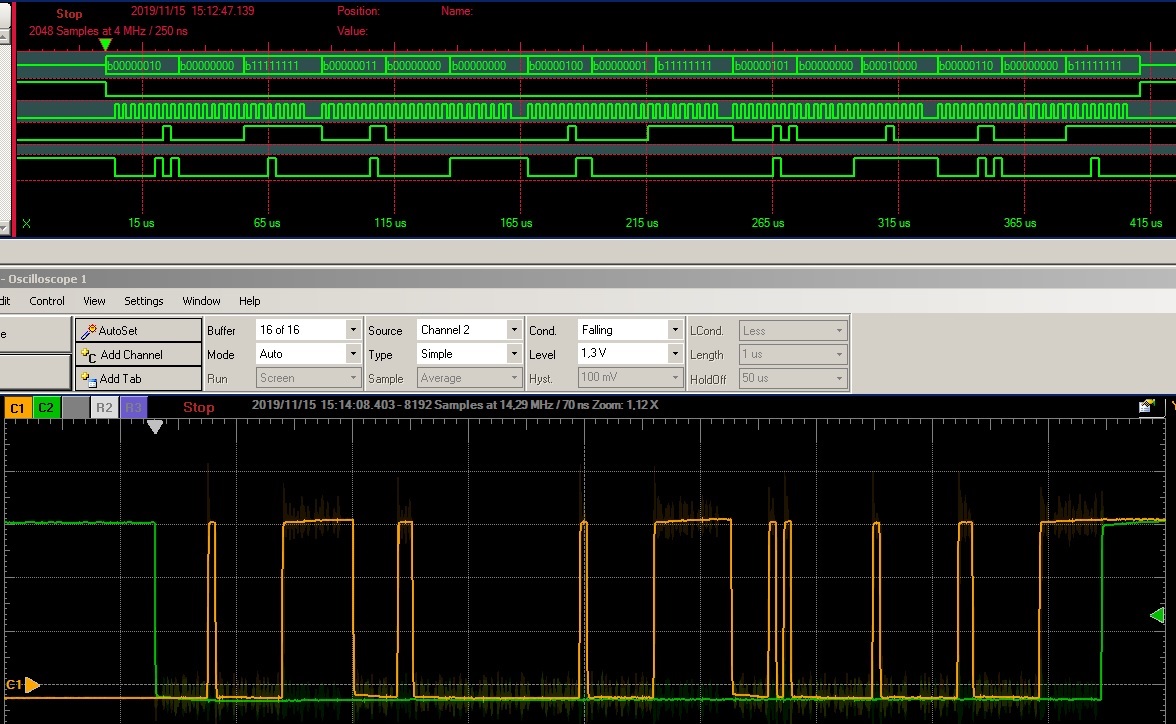
    I tried to do according to your recommendations. Unfortunately it didn't work. Look at the screen please:

    What do you think about it?
    I have a question about reading the ID. To read ID I need to send Address Bits first?

    Thank you and best regards
    Andrew

  • Hi Andrew,

    1. I see that you are using a continuous CS frame for this.  This not supported in stand-alone operation.  You need to bring CS high between each write command. As this device was created to support daisy chain operation, only the last command will be latched.

    2. To read a register you issue two commands: the first is the read command (0x81 0x00 0x00), the second command can be any SPI transaction, but the readback data is clocked out on that command.  For example, you could use a NOP command (0x00 0x00 0x00).

    Thanks,

    Paul

  • Paul,


    Indeed, I have not read about CS.

    Unfortunately, I still haven't been able to start the DAC.
    Look at these registers, please:

    uint8_t ID_READ[] = { 0x81 , 0x00, 0x00 };
    uint8_t ID[] =         { 0x01 , 0x00, 0x00 };
    uint8_t SYNC[] =     { 0x02 , 0x00, 0x00 };
    uint8_t CONFIG[] =  { 0x03 , 0x00, 0x00 };
    uint8_t GAIN_[] =     { 0x04 , 0x01, 0xFF };
    uint8_t TRIGGER[] = { 0x05 , 0x00, 0x00 };
    uint8_t BRDCAST[] = { 0x06 , 0x00, 0x00 };
    uint8_t STATUS[] =     { 0x07 , 0x00, 0x00 };

    I send it this way:

        SPI_1_CS_ON;
        HAL_SPI_Transmit(&hspi1, SYNC, 3, HAL_MAX_DELAY);
        SPI_1_CS_OFF;
        HAL_Delay(1);
        SPI_1_CS_ON;
        HAL_SPI_Transmit(&hspi1, CONFIG, 3, HAL_MAX_DELAY);
        SPI_1_CS_OFF;
        HAL_Delay(1);
        SPI_1_CS_ON;
        HAL_SPI_Transmit(&hspi1, GAIN_, 3, HAL_MAX_DELAY);
        SPI_1_CS_OFF;
        HAL_Delay(1);
        SPI_1_CS_ON;
        HAL_SPI_Transmit(&hspi1, TRIGGER, 3, HAL_MAX_DELAY);
        SPI_1_CS_OFF;
        HAL_Delay(1);
        SPI_1_CS_ON;
        HAL_SPI_Transmit(&hspi1, BRDCAST, 3, HAL_MAX_DELAY);
        SPI_1_CS_OFF;
        HAL_Delay(1);
        SPI_1_CS_ON;
        HAL_SPI_Transmit(&hspi1, DAC_1, 3, HAL_MAX_DELAY);
        SPI_1_CS_OFF;
        HAL_Delay(1);

    But I was able to read something from the DAC:

    Name : SPI_RecivedData
        Details:"\201(\226"
        Default:0x20000243 <SPI_RecivedData>
        Decimal:536871491
        Hex:0x20000243
        Binary:100000000000000000001001000011
        Octal:04000001103

    Can you read something from this?

    Greetings,

    Andrew

  • HI Andrew,

    The data you read back is 4 bytes long.  Do you know how that data is justified? The command should only be three bytes.

    With your SYNC configuration, the TRIGGER and BROADCAST commands are not necessary.  

    If you write:

    SYNC = 0x0000

    CONFIG = 0x0000

    GAIN = 0x01FF

    DAC1 = 0x8000

    Then the DAC should be 1.25V.  

    Is that working?

    Also, what are your supply values? Can you confirm that the reference pin is 2.5V.

    Thanks,

    Paul

  • Hi Paul,

    Is the first success! :-)
    After uploading the configuration bits, 1.25V appeared on the DAC output.


    The supply voltage is 3.3V (VDD, VIO). REF is 2.5V with ground capacitor.


    I was able to get the ID. However, they are 3 bytes:

        Hex:0x81
        Binary:10000001

        Hex:0x28
        Binary:101000

        Hex:0x96
        Binary:10010110

    Does this look good?

    The problem is when I send some DAC value. E.g:

    uint8_t DAC_1[] =     { 0x08 , 0xF, 0xFF };  //Sample value of the variable sent to the DAC1

            SPI_1_CS_ON;
            HAL_SPI_Transmit(&hspi1, DAC_1, 3, HAL_MAX_DELAY);
            SPI_1_CS_OFF;

    Then the DAC voltage is 0.16V. Below is the SDI signal view:

    Paul, what could be wrong?

    I am very grateful for your help ...

    Greetings,

    Andrew

  • Hi Andrew,

    Just a minor problem with your code.  The DAC registers are left-aligned:

    You should be writing :DAC_1[] =     { 0x08 , 0xFF, 0xF0 }; 

     By writing 0x0FFF, you have actually written 0x0FF to the DAC, which is about (1/16)×2.5 = 0.156V.

    You should just left-shift your data 4 bits.

    Decoding your Device ID register:

    Your result of 0x2896 shows that you are a using a 12-bit, 8-channel, reset-to-midscale device.

    Thanks,
    Paul

  • IT WORKS! :D


    Paul, I understand everything now. You pointed out that everything is written in datasheet. I'm a beginner and I'm just learning.


    THANK YOU VERY MUCH FOR YOUR HELP. This integrated circuit stays in my project.


    Best regards to you


    Thank you!
    Andrew