This thread has been locked.

If you have a related question, please click the "Ask a related question" button in the top right corner. The newly created question will be automatically linked to this question.

ADS1299: Not sure if the internal reference is working properly....

Part Number: ADS1299

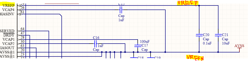
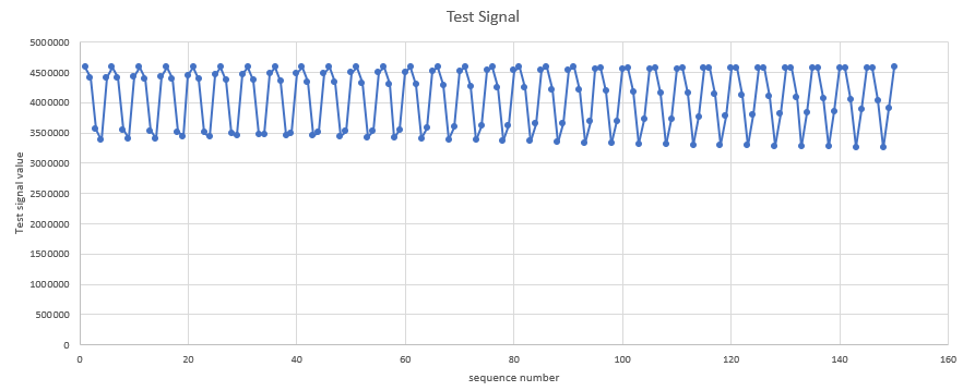
I have made the schematic according to the data sheet and the SPI communication works fine.  when i read the test signal data and visualize them , all what i am seeing is sinusoidal.  
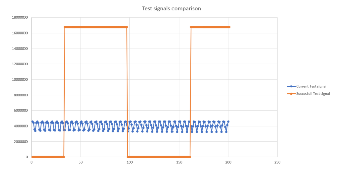
when i tries changing the test signal to DC , the same sinusoidal appears, not much change in amplitude is also visible. 

But reading the registers again the values read are correct (same as written)

Is there any other way to test the internal reference ? 
any plausible reason of what is causing this ? 
is it possible that soldering heat damage is causing this ?

  • Hi Praga,

    When you read the registers, is the device ID returning correctly?

    You can measure the reference voltage across VREFP and VREFN. 

    Is this being done using the demonstration kit or your own design? 

    Pictures of the waveform, schematic, pcb, etc may help. 

    You can use the BIOFAQ to verify that your device is still functional; https://e2e.ti.com/support/data-converters/f/73/p/772058/2855202

  • yes i am able to read the registers and they are returning the correct values. 

    This my own design based on the ads1299EVM board. 

    When measured the voltage across VREFP and VREFN we are not getting 4.5v, so we measured across the VCAP1 , that is quite less as well (less than 0.2v). 

    This is the schematic which is implemented 

    These the waveform which we are getting at the output (despite any frequency mux setting ) 

  • Hi Praga,

    This looks like it could be a few things to me. First, use the BIOFAQ located here to verify that your device is still functional since VREF and VCAP may not be reporting correct values: https://e2e.ti.com/support/data-converters/f/73/p/772058/2855202

    Second, the waveform looks like a data collection issue that is often caused by under sampling. This is the internal test signal, correct? If so, there should not be any issue with a properly working ADS1299 sampling this signal accurately. I expect to see many more points per period than what is shown (6).  I would make sure that the MCU is capturing all data points from every DRDY pulse. 

    Please verify these two things and let me know what you find. 

  • 1) the voltages acorss  VCAP1 is way below (almost 0.1v). , a similar situation in VREF too. 

    2) We collected test signal data (all channel data are treated as unsigned) with ADS1299EEG FE board with Arduino. It was successful. We plotted it along with the current unsuccessful test signal data shown below. Both test signals are produced with same amplitude and frequency
    As we are using polling method for data acquisition from ADS1299 in our Atmel Xmega microcontroller it is possible to miss some data, but the Arduino board which used to collect the correct test signal data (Orange curve) also used same polling method and it also missed some samples but still able to produce the correct curve. Also Xmega runs with 32 MHz and Arduino runs with 16 MHz clock. Further the current test signal data (Blue curve) does not seem to be caused by undersampling. It can be easily seen from the amplitude of both signals.

  • Hi Praga,

    Since VCAP1 and VREF are reporting incorrect values, it makes sense that the device will not be outputting properly. Are you able to work through the rest of the debug steps in the post I linked? The additional /RESET is essential to the power-up of the device. Another thing to consider is replacing the device to rule out manufacturing/handling damage as you mentioned in your first post.