This thread has been locked.

If you have a related question, please click the "Ask a related question" button in the top right corner. The newly created question will be automatically linked to this question.

ADS1294R: "Signal rise" and signal offset

Part Number: ADS1294R

Hi,

We have integrated ADS1294R in a medical device. There is only 2 electrode, no RLD electrode.

We have several questions regarding the ADS behavior :


1°) "Signal rise" : We notice the following behavior


We configure ADS on device startup, then we set it on STANDBY.

When a mesure is requested, we send a WAKEUP command and wait 10 ms before issuing RDATAC.

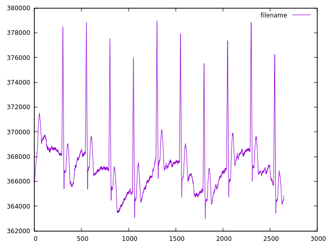
If we remove STANDBY and WAKEUP command, there is no more "signal rise" :

But in the signal, the first two measure seems wrong :

Raw values :

536693
424506
366349
365874
365993
366101
366187
366186
366358
366598
366729

If we ignore these 2 first measures, the signal looks fine :


2°) If we look at previous signal, the values are not centered on 0, there is an offset. What is/are the cause(s) of this offset ?

3°) In ADS datasheet, we can use internal signal reference. The documentation indicates signals are similare to  the CAL signals described in IEC60601-2-51. Actually I get a square signal, that's no correct, is it ?

Thank you.

  • Hello Charles,

    Thank you for your post.

    Are your ECG electrode inputs AC- or DC-coupled? 

    The inputs to the ADS1294R must remain within the input common-mode range of the internal PGAs. If the inputs are DC-coupled and you are not using an RLD electrode, the DC bias point of the body is left floating with respect to the ECG circuitry. It is possible for the electrode inputs to "self-bias" due to the presence of small leakage currents, but this is less deterministic and can vary widely as the input impedance of the electrodes changes.

    STANDBY places the device into a low-power state where all circuitry is shut-down except for the reference. This may change the input impedance and leakage current present on the input channels. Upon waking up the device, any current in the signal path will produce an R-C time constant as the voltage settles to some common-mode value.

    As you first begin collecting data, the first 3 samples (i.e. first 3 /DRDY falling edges) should be ignored. This is necessary because the digital filter in a delta-sigma ADC requires some history before the output data is considered settled.

    The ADS1294R offers both DC and AC (square-wave) test signals. These can be helpful in verifying that the device is operating normally after start-up.

    Best regards,