This thread has been locked.

If you have a related question, please click the "Ask a related question" button in the top right corner. The newly created question will be automatically linked to this question.

ADS1299EEGFE-PDK: Problem achieving the lower noise floor for this amplifier model

Part Number: ADS1299EEGFE-PDK
Other Parts Discussed in Thread: ADS1299, TLV6741

Hi,

I recently purchased this PDK. I replaced the bias filter in order to include 150 Hz BW instead of 41 Hz BW(which comes as default) Because I wanted to get rid of the 50,100 and 150 Hz noise from power lines. 

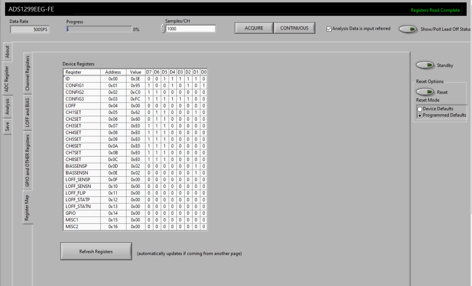
I configured one channel to be used with bias electrode(selected appropriate sense bits for derivation). Used short electrodes with GND shield. Confirmed the bias electrode function by measuring the bias voltage from another channel. Using bipolar power supply and batteries are used to power the PDK.

But still I am not getting a decent noise floor as expected from this amplifier. Noise floor(pk - pk) seems to be around 10-20 uV. Please let me know the some suggestions to improve or find the cause of this.

Thanks,

Saba

  • Hello Sabra,

    Thank you for your post.

    Can you please share the complete register map settings? The noise floor will be most dependent on the data rate and the PGA gain.

    It makes sense that you would increase the R-C filter cutoff frequency for the BIAS amplifier to cancel the second and third harmonics of 50 Hz. What is the output of the BIAS amplifier connected to? I imagine you are shorting INxP, INxN for one channel and BIASOUT together?

    Best regards,

  • Hi Ryan, 

    Thank you for your response. Please find the register map settings attached. I connected it to a subject in development environment, with many different electrode configurations, but couldn't get a signal less than 10 uV (pk - pk) . Is there any modification needs to be done for the RC filter of the INxN , INxP?  

    I am a new to this EMG playground and would appreciate your support to get started with this low noise amplifier. 

    Kind Regards,

    Saba

  • Hello Saba,

    There are several factors which will contribute noise to the signal chain. At 500 SPS, Gain = 24 V/V, the ADS1299 itself contributes 1.39 uVpp of noise (typical), but this is not the limiting factor. Noise will also couple onto the body, the electrode wires, and the PCB. The input RC filters are not intended to filter out this noise - they are used to prevent higher frequency noise from aliasing.

    The active BIAS electrode will help suppress some of the common-mode noise on the body, but some of this noise may still convert to a differential noise due to mismatches between the INxP and INxN signal paths. This includes contact impedance from the electrodes, which can vary quite a bit. The best you can do is to match the components as closely as possible using very low tolerance components. Most EEG applications still require additional averaging and other post-processing algorithms to reduce the noise further. I think with 10 uVpp, you're already very close!

    Best regards,

  • Thank you Ryan,

    Apologies for the late response and thank you for your detailed response. Please help me with the following questions.

    1) If the bandwidth of interest is 300 Hz, does decreasing the bandwidth of those anti aliasing filters to somewhere around 800Hz help (without affecting the fMod)? I am thinking of minimising the components in the analog path to increase the CMRR.

    2) Could you please recommend the components needed for the bias shield circuitry or suggest how to choose them?

    Kind Regards,

    Saba

  • Hello Saba,

    The -3 dB bandwidth of the digital filter is about 0.262 * f_DATA. At 500 SPS, this gives you a -3 dB bandwidth of about 131 Hz. I do not see a benefit is reducing the cutoff frequency of the antialiasing filters. 

    The shield drive circuitry can be as simple as a unity-gain voltage follower with limited filtering. A general purpose amplifier such as the TLV6741 would work fine.

    Best regards,

  • Hello Ryan,

    Thank you for your response. 

    Does it means that the amplifier is converting signals reliably if they are under 131Hz? 

    How does the 0.262 calculated? is that amplifier specific?   

    Thank you for suggesting the amplifier for shield drive.

    Kind Regards,

    Saba 

  • Hello Saba,

    The ADS1299 is a delta-sigma analog-to-digital converter (ADC). There are some peripheral amplifiers included, but it is primarily an 8-channel ADC.

    The ADCs are followed by a digital filter that decimates the output and contains a low-pass filter response. This response scales with the ADC output data rate as detailed in Figures 27 - 31.

    Best regards,

  • Hi Ryan,

    Thank you for your response, it really helped to clarify many doubts. Currently we are at the stage of developing a prototype. 

    1: I saw the data sheet and would like to know why we need the anti aliasing filters if the bandwidth at 500Hz  is 131Hz.  Is it meant to be active when using higher data rates?

    2: If my bandwidth of interest is exactly the same as -3dB bw(131Hz) of the amplifier. Do I still need to have an anti aliasing filter for inputs? 

    3. Is there any impacts to the biopotential signals measured by this amplifier when using a patient protection resistor around 110K?

    Appreciate your prompt response.

    Kind Regards,

    Saba

  • Hello Saba,

    I'm glad to provide some help.

    Antialiasing filters help remove higher frequency noise from the output. This noise may not exist directly in the bandwidth of interest, but it may alias inside the ADS1299. The digital filter response shows you where it passes higher frequencies and leaves them prone to aliasing. It's recommended to design the antialiasing filter bandwidth to be 10x wider than your bandwidth of interest, so as not to interfere with the signals you're measuring. For more information, I recommend reviewing some of the frequency analysis training material we've recorded in TI Precision Labs - ADCs.

    I believe it is common to include such large protection resistors in series with electrode inputs. The impedance of electrodes can be large anyway. The main concerns with this component to be aware of include:

    1. Input bias current will create a voltage drop across the protection resistor. This may increase DC offset.
    2. Mismatch between channels is dependent on component tolerance. Keep the tolerance to < 1% to maintain good CMRR.

    Best regards,

  • Hi Ryan,

    Thank you for your response. The training was very useful. 

    May I know the reason for why the anti aliasing filter needs to be 10x wider ? What would be the negative effect if we choose it close to the bw of interest?

    Would you recommend using anti surge resistors of higher value for patient protection resistors instead of using TVS diodes to clamp the voltage? 

    Kind Regards,

    Saba

  • Hi Ryan,

    I appreciate your response on this.

    Kind Regards,

    Saba

  • Hi Saba,

    The 10x wide bandwidth for antialiasing filters was just a suggested "rule of thumb." Even if you're -3dB cutoff is equal to your bandwidth of interest, you will observe some small attenuation at frequencies even a decade earlier. You do not want the passive filters at the ADC inputs to attenuate your signals of interest.

    I don't have a lot of expertise in patient protection, but most applications would require a combination of both. There needs to be some series impedance to limit the flow of DC current to the patient. TVS diodes are used to project the electronics (i.e. the ADC itself). The min/max voltages need to be clamped within the device's Absolute Maximum Ratings table. Additional resistance is sometimes used between the diode connections and the ADC input pins to limit current in the event that the TVS diodes and internal ESD diodes clamp to different voltages. A lot of the input protection component selection depends on the exact standards you're trying to meet.

    Our Precision Labs - ADCs training portal does have some presentations on Electrical Overstress, which you may find applicable to your design.

    Best regards,