This thread has been locked.

If you have a related question, please click the "Ask a related question" button in the top right corner. The newly created question will be automatically linked to this question.

ADS1240: Digital Filter rejection after data rate change

Part Number: ADS1240

We are using the AD1240 in a measurement system that requires very good rejection of differential mode mains noise (50Hz/60Hz and harmonics).

Ideally, the converter would run continuously at a data rate of 15Hz - we have tested this and rejection of mains frequencies is excellent.

If the the converter runs at 7.5Hz then changes to 15Hz how long must we wait until we get the correct filter response again?

  • Hi Mike,

    Welcome to the E2E forum! The ADS1240 is single-cycle settling, so following the register write command to change the data output rate, the next transition of DRDY from high to low will signal a new conversion result is ready.  The period of time will depend on the data rate value written to the register relative to the last edge of SCLK following the register write command.  The question from my perspective is whether or not the digital filter is reset and a new conversion starts when the register write takes place.  Our new devices will reset the digital filter starting a new conversion on certain register writes.  However I do not believe this is the case for the ADS1240, but I cannot find specific documentation that tells me one way or the other.  My hypothesis is built around the fact that there are specific timing requirements relative to when a mux change takes place following DRDY without having issues with one channel affecting the other.  I would suggest issuing a DSYNC either by pin or command following the register write to change the output data rate.  Using DSYNC will restart the conversion at the currently selected output data rate.

    Best regards,

    Bob B

  • Hi Bob,

    Thanks for your reply. We will try the DSYNC, but I also thought some more information would be useful.

    We have some test code that just configures the ADC and runs continuously at 15Hz - noise rejection is really good.

    The measurement code operates as follows:

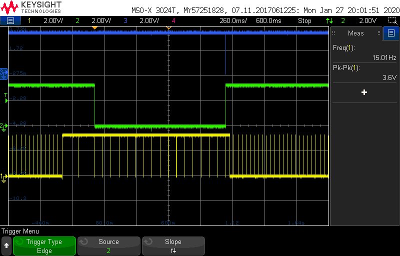
    Blue trace = /RESET pin, Green trace = external zero applied to ADC when high, Yellow trace = /DRDY pin

    Measurement starts when zero (green trace) goes low and the ADC is set for 15Hz.  The first 4 samples are discarded and the remaining samples averaged until the measurement ends ( zero goes high, and ADC is reset).

    The noise rejection (50/60Hz) of measurement using this sequence is not very good at all, and this is what we need to improve.

    I hope this additional information helps.

    Mike

  • Hi Mike,

    I'm not quite sure that I'm following what you are actually doing.  You stated that "Measurement starts when zero (green trace) goes low and the ADC is set for 15Hz.  The first 4 samples are discarded and the remaining samples averaged until the measurement ends ( zero goes high, and ADC is reset)."  However that is not what I see in the scope shot. 

    I see that while the green trace is high, the ADC is switched to 3.75 Hz and 2 conversion results are read from the device (or perhaps registers are being written within this time), but definitely the timing has switched to the slowest conversion rate, and then at about the same time as the green trace goes low and then the data output rate switches to 7.5 Hz.  Lastly when the Reset pin is pulsed and the green trace goes high, the ADS1240 returns to 15 Hz output rate.

    Can you send me the raw data (no averaging or calculations) throughout this measurement period for the cases where you use 15 Hz and 7.5 Hz?  I would like to compare the data.

    One potential issue is the stability of the power line-cycle frequency and the master clock frequency relative to each other.  The FIR filter becomes much steeper as the data rate decreases.  If a nominal 50 Hz line-cycle frequency is actually 49 Hz and if the clock frequency is slightly skewed from 2.4576 MHz, then you could see a point where 15 Hz may appear better than 7.5Hz.  Crystals can be pulled or skewed from the nominal frequency depending on loading.  Verify the frequency of the master clock is what you would expect.

    Best regards,

    Bob B

  • Hi Bob,

    Thanks for your reply.

    I have been unable to get raw data, as the firmware engineer has moved on to other issues at the moment.

    I think this is a firmware configuration issue as some operation modes are fine.  

    The firmware engineer will investigate as soon as he is available, and I will get back to you if we still have an issue.

    Thanks,

    Mike