This thread has been locked.

If you have a related question, please click the "Ask a related question" button in the top right corner. The newly created question will be automatically linked to this question.

ADS131A02: ADS131A02 SPI no data

Part Number: ADS131A02

Hello,

I use ADS131A02 with microcontroller and I have problem with data channel. I read always 0x00 for the data channel.

Configuration:

M0 = float

M1 = GND

M2 = GND

Interface mode : Synchronous slave mode

Reading and writing registers works correctly and when I send command, I receive correct ACK.

Initialisation set up:
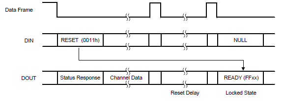
  • Reset
  • UNLOCK command and I receive 0x0655
  • Configure Device, enable channel.
  • The written registers are correct
  • Write 0Fh to the ADC_ENA register to enable channel
  • WAKEUP command
  • LOCK command

Thanks,

  • Nico,

    There is currently a similar post on e2e, where someone else is having a problems getting data out of a device using synchronous slave mode. While you don't have a daisy chained second device, you are using synchronous slave mode. Here is the post that I was referring to: 

    https://e2e.ti.com/support/data-converters/f/73/p/877552/3246867

    I believe that he's at least able to get data out of the first synchronous slave device.

    It'll take me some time to read through both your posts and try to help debug them. For now read through my comments on the other post and see if it helps. 


    Joseph Wu

  • Hello Joseph,

    Thank you for you reply. I will read this post.

    Nico

  • Nico,


    Sorry about the delay. I wanted to check to see if you were able to get any data out of the device.

    In your sequence, After the LOCK command, you should get the 0555h response in the next communication frame. When you read the ADC data, what response are you getting from the ADC? If you are sending the NULL command to read ADC data you should read the STATUS of the device for the first device word of the frame, which would start with 22xx.

    Are you getting 000000h data for more than the first 4 data reads/frames?

    Joseph Wu

  • Joseph Wu,

    When I sending NULL command, I read : 0xFF02

    Nico

  • Nico,

    Can you go back and check your code for a reset somewhere? You can check based on the responses that you get for each command that you send. If you get the 0xFF02, this may mean that the device has been reset. This would also mean that the device is back at it's default state and the registers are also locked. 

    When I asked about the read, I was expecting the 0x22xx response based on sending the NULL to the device. This is what it would have looked like:

    The REG(STAT_1) would have been the 0x22xx response. However because you were gettting 0xFF02, this may mean that the device has been RESET. It may have been reset by command, by pin, or by powering off the device. This is what would happen with a reset:

    If you have a logic analyzer, you should be able to look at the commands sent to the device, and the device response in the next word frame. You could verify all the communication between master and the ADS131A02.

    Joseph Wu

  • Joseph,

    Thank you. I solved my communication problem with CLKPhase = 1. Now, I receice correct ACK when I send 0x0655.

    When I send NULL command, I receive 0x2220.

    Nico

  • Nico,

    Just to make sure, are you able to collect data now? In your sequence, you show a WAKEUP, NULL , UNLOCK, NULL, with the corresponding responses. I would note that on page 79 of the datasheet there is a flow chart showing the start up of the device, with suggestions for commands. You should be able to follow the flow chart get the ADCs running.

    I'll close this post for now, but if you haven't gotten the device operational, post back and we can continue to work on this thread.


    Joseph Wu

  • Hello,

    I'm still having trouble reading the adc data.

    When I read the STAT_1 register, I read 0x10.

    • Register STAT_P = 0x03
    • Register STAT_N = 0x03

    I don't understand why I have input pin exceeds the set threshold. When I force the input AIN1P to AVSS, I have the same result.

    • AVSS = 0V
    • AIN1N = 0V
    • AIN1P = 0V

    Thanks,

  • Nico,


    Because the AINP and AINN = 0V, the input will be very close to AVSS. Unless the negative charge pump is enabled, the STAT_P and STAT_N will warn you that the input to the ADC is close to either AVDD or AVSS. With COMP_TH[2:0]=000, this threshold is anytime the inputs are within 5% of the rail. If your supply is 3.3V, then the STAT_P or STAT_N will be flagged anytime an input pin is greater than 3.135V or lower than 0.165V. By tying inputs to ground both inputs would be flagged. Figure 42 shows the COMP_TH[2:0] setting the threshold level against the supplies. The results are latched into the status registers.

    Threshold values are shown in the A_SYS_CFG register, and they set as a percentage of the supply voltage.

    The flags are just a warning. AVSS and AVDD are valid inputs I would also note that whatever you are measuring must have a common ground between your sensor and the ADC and microcontroller. If the sensor is a floating voltage, the flags may be tripped.

    When you tie the inputs together at the ground, are you still getting data? What values are you reading for the conversion?


    Joseph Wu