This thread has been locked.

If you have a related question, please click the "Ask a related question" button in the top right corner. The newly created question will be automatically linked to this question.

ADS131A04: Multiple Devices Synchronous Slave Mode - Data not shown when ADC's enabled

Part Number: ADS131A04

Hello,

We are using two ADS131A04 as a chain in Synchronous Slave Mode, CRC disabled, 24 bits, Hamming code off, and a free running SCLK (7.8125 MHz).

We are using an internal reference, AVSS -2.5 AVDD 2.5 IOVDD 3.3

Tested input signal is 1kHz sine wave with 2~3V pk-pk (0 to 2~3)

We have the same schematic as in the ADS131A04EVM.

We are not getting any data out after enabling the ADCs, and we did most of the configurations as in the datasheet so we are not sure if we missed a step.

The following register configurations were done:

A_SYS_CFG (0Bh) - 68h

D_SYS_CFG (0Ch) - default

CLK1 (0Dh) - 82h

CLK2 (0Eh) - default

ADC_ENA (0Fh) - 0Fh

and the rest of the user configured registers were left at default.

This is the following commands that we did to enable the ADC, the commands were done one after the other and their response was checked with the datasheet before doing them all at once.

UNLOCK

WREG 0D 82

WREG 0B 68

WREG 0F 0F

WAKEUP

LOCK

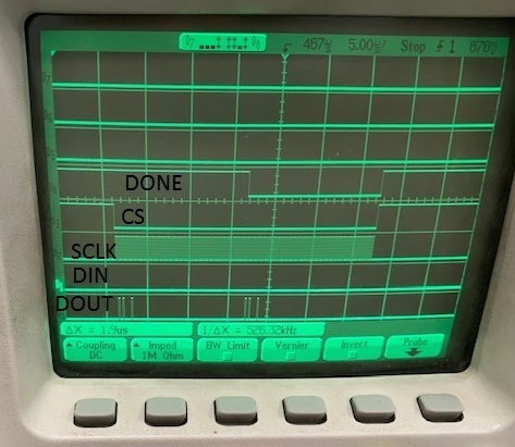
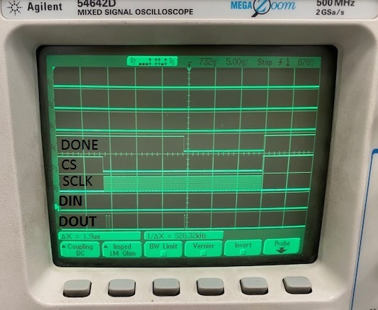
The following pictures show what we are getting from the scope, we got some fault for /DRDY but not as frequently which is why we are not sure if this is the sole problem

and this is what we got:

We checked all the registers to make sure we are configuring them correctly, and all gave us back wanted results. both DONE and CS/ /DRDY frequencies match.

Do you have any idea what the problem might be? We had a problem previously for not getting a response from the second device, but the problem was fixed by sending the command after the DONE goes low for the second device.

  • Shada,


    Are you getting 0s for the output data of the second device? Is the second device not sending out /DRDYs? It appears that you have the channels to check this with your mixed signal digital scope. I would look at the /DRDY to verify that the device is actually converting. I would also note that there is some latency on the data output, which I explain below.

    This device has a sinc3 filter, which means that it reports a moving average of three conversions. I'm not completely sure if the output is suppressed until the digital filter is full (meaning that the output stays 0s for the first three conversions), however it may for this device. Additionally, this device has an output data buffer to read from DOUT. That means that even if the settled output data is collected by the 3rd ADC conversion, there is one more delay of conversion time until the ADC outputs the data. This means that the output data will be ready by the fourth /DRDY pulse.

    At the minimum, you should be able to see that the /DRDY pulse is transitioning from high to low at the data rate. This will tell you that the second device is converting. After that, check that the output data is coming out of the ADC by the 4th /DRDY pulse.


    Joseph Wu

  • Shada,

    I'd forgotten that for this setup, you're using synchronous slave mode. In that case, the /DRDY is an input for synchronizing the conversions. Normally I think of the ADS131A04 in asynchronous interrupt mode, where you configure the device, the device starts converting, and the /DRDY transitions low to let the master know when each conversion completes. /DRDY is used as an interrupt for the master to read the device. 

    Most instances of using the a device in synchronous slave mode would be using a first ADS13104 as a master, and then one or more synchronous slaves as in a daisy chain. This way, the /DRDY of the first device is used as the synchronizing pulse for the other synchronous slaves. This is the way it is shown in Figures 96 and 98 in the datasheet. While you can use all devices as synchronous slaves as in Figure 100, I find this a bit more difficult to do this.

    I'll need to spend a bit more time reading through your setup sequence. For now, I would start by enabling the device, waiting about 5ms, sending a synchronizing pulse on /DRDY and then check to see that the DOUT read comes up all zeros for an extended period of time (more than 4 x data period, many more if possible).

    Joseph Wu

  • Shada,

    One other thing, how do you have the master clocks from the devices connected? Are you using a clock from the master feeding CLKIN?

    Joseph Wu

  • Hello Joseph,

    Thank you for your response, I will try your suggestions first thing tomorrow morning.

    For now i can answer regarding the clocks, both devices are in synchronous slave mode and an FPGA is the master.

    I am only sending a clock through the SCLK from the FPGA and I connected CLKIN to gnd and left XTAL2 floating per the data sheet instructions. This is true for both devices .. same SCLK and CLKIN grounded

    I will get back to you with updates later tomorrow.

  • Shada,

    Ok, thanks for letting me know about the clock. I was worried that you were using crystals for the devices. If there was any small difference in the clock frequency, then the devices would be difficult to synchronize. If the master and the devices have the same clock, it should be fine.

    I'll get back to you soon.

    Joseph Wu

  • Hello Joseph,

    We made few changes and currently the issue we are facing is regarding synchronization.

    First, we made SCLK continuous rather that it being Low when device is idle (CS high).

    Second, we switched to fixed frame and added the extra zeros for CRC at the end twice for each device.

    Third, we are trying to sync the data rate and the CS/ /DRDY but we are not sure that it is working properly. Before I dive into this issue I will tell you our command sequence again.

    Configurations:

    A_SYS_CFG (0Bh) - 68h

    D_SYS_CFG (0Ch) - 3E

    CLK1 (0Dh) - 82h

    CLK2 (0Eh) - default

    ADC_ENA (0Fh) - 0Fh

    Command:

    UNLOCK

    WREG 0D 82

    WREG 0B 68

    WREG 0C 3E

    WREG 0F 0F

    WAKEUP

    LOCK

    Since we are using two devices in daisy chain, the commands are sent in 24 bits words as the following (command,24'h000000,24'h000000,24'h000000,24'h000000,24'h000000,command,24'h000000,24'h000000,24'h000000,24'h000000,24'h000000)

    from the response it seems like both devices are OK and responding but only a time issue remains.

    After enabling and locking the ADC we are getting the following status : 2204h

    Our SCLK coming from the FPGA is 7.63MHz, from the Table 29 and Table 30 we calculated our fdata rate to be (7.63MHz/(8*400)= 2.384kHz 

    From the datasheet, it was mentioned that the data rate and DRDY need to be the same frequency or multiple thereof, does this have to be exact because we keep getting the F_RESYNC high at every CS toggle.

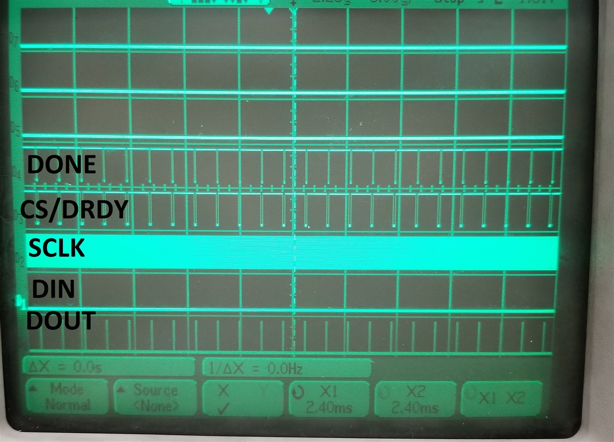
    Zoomed out image:

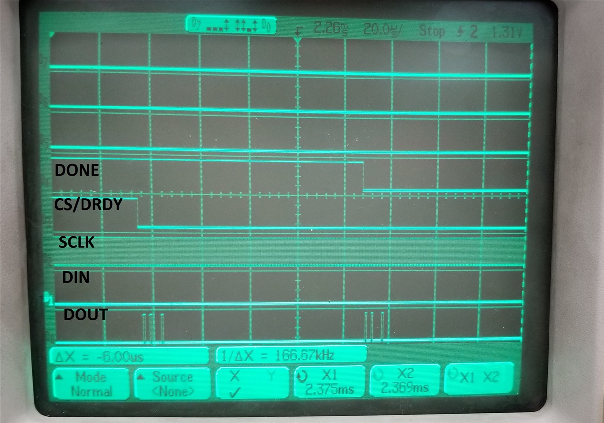
    Zoomed in:

  • Shada,


    Sorry about the delay. I've looked through your sequence and it looks like it should work. There's nothing unusual about the setup that I can see. I would note that the ADC response after the LOCK coming from WREG 0F 0F should be 0555h. That would come as a response in the next frame. If you sent a null command in the next frame, the frame after would be the STATUS response which would be the 2204h response with the F_RESYNC error.

    If you set CLK1 to 82h, then the SCLK coming from the FPGA is used as the ADC clock source. I would note that the timing for the data rate and the /DRDY synchronization must be exact or the device will give the F_RESYNC flag.

    For your setup, it seems like your math is correct. The 7.63MHz for the SCLK, is used for clock source. The ICLK_DIV is 8, and the oversampling is 400. Instead of calculating the data rate, I think you need to count the number of SCLKs in the data period. With the given SCLK rate and configuration, this would be 1600 clock cycles. I think there will also be some tight timing with SCLK to the /DRDY synchronization which is shown in Figure 5.

    One thing you might try would be to start with no /DRDY pulses just to check the ADC read. I would note that if you don't get the timing right, you will eventually lose synchronization, which might cause you to skip a read or read a data twice eventually depending on the timing of the data read. In synchronous slave mode, I still think you'd want the /DRDY to verify the master timing though.


    Joseph Wu

  • Hello Joseph,

    Thank you for the reply!

    I have DRDY and CS shorted together per the setup recommendation when using multiple devices as in Figure. 100.

    So I was not sure if what you mentioned for me to try would work as CS has to be zero to check the ADC read.

    Did I do the set up correct in terms of schematic or i I have to have two separate DRDY inputs for each device?

    My sync timing t_su(sync) and t_h(sync) are both equal to 156ns so I am assuming it is okay as they are more than the 10ns minimum noted in the Timing table.

    Thank you,

    Shada

  • Shada,


    The schematic in Figure 100 is correct, you could use the /CS to select the device for SPI communication and you could also use that same /CS to trigger the /DRDY to synchronize the devices for synchronized slave mode. However, the synchronization pulse is optional as is shown on Figure 5.

    If you started the device without the optional /DRDY pulses (no pulses on /DRDY at all), the data could be retrieved without device constantly re-synching. I suggested that the /DRDY not be pulsed so that we could check to makes sure that the data is coming out of the device. If the timing of the synchronized pulse is incorrect, this becomes difficult to debug.

    If you can't separate /CS from the /DRDY, I think you may need to play with the /CS timing. Again, I think that with your settings, there would be 1600 SCLK cycles After the first read, count the number of clock cycles from the fall of the /CS to the next fall of /CS. Just in case, there's something we missed, vary this timing from from 1590 to 1610 SCLK and read 10 data points for each case. For each data read, I would check the result from NULL command response for each of these reads. Note that the NULL response gives the STAT_1 reading each time, and you can check to see if the F_RESYNC flag is set each time.

    You could also vary this timing at a much larger range and see if we've missed the data rate calculation. You'd read the F_RESYNC flag for each of the NULL commands used for reading data.


    Joseph Wu

  • Shada,

    I haven't heard from you for a while, so I thought I'd check on your problem. I know that setting the sync pulses in synchronous slave mode without having a synchronous master (as in a daisy chain) is difficult because you don't have visibility in to the slave's timing.

    I'll close this thread for now, but if you still have problems, post back and we'll continue to work on this issue.

    Joseph Wu