This thread has been locked.

If you have a related question, please click the "Ask a related question" button in the top right corner. The newly created question will be automatically linked to this question.

ADS1298: How to properly bias an animal recording brain/cardiac signals?

Part Number: ADS1298

We are performing some recordings while an animal is under anesthesia using the ADS129x family. Line noise is not expected to be a problem (everything is on battery in our surgery suite). My question is how I should approach using the BIAS, if at all? I have been recording my own cardiac rhythms using simple TEMS pads, but no matter what configuration I use I have a huge DC bias in my signal. I thought the RLD was supposed to counter that? If I don't expect line noise, could I drop the RLD altogether and would I just leave the animal's body "floating"? My circuit is below. Thanks!

  • Hi Matt,

    I would not recommend leaving the animal floating as the floating potential may be outside of the common-mode input range of the input PGA, which would lead to clipping. 

    The RLD/BIAS drives a certain potential on the patient, typically mid-supply or derived from the input electrodes, to ensure that the measurement is within the common-mode input range of the PGA. Once the measurement reaches the PGA, the potential is canceled out via the common-mode rejection ratio. 

    Your circuit looks fine to me. Can you post your register settings and provide a little more detail on this DC bias you're seeing at the output? 

    Here is a link to the BIOFAQ, there is an application note covering RLD if you would like more information: https://e2e.ti.com/support/data-converters/f/73/p/772058/2855202

  • Thanks for the quick response, Alex! I suspected floating was a no-go. Here are my configs:

    ads_wreg(0x01, 0b01000110); // config1
    ads_wreg(0x02, 0b00010001); // config2
    ads_wreg(0x03, 0b11001100); // config3
    ads_wreg(0x0D, 0b00000001); // RLD_SENSP
    ads_wreg(0x0E, 0b00000001); // RLD_SENSN
    byte chReg = 0b00000000; // XXXXX101 for test, 000 for normal

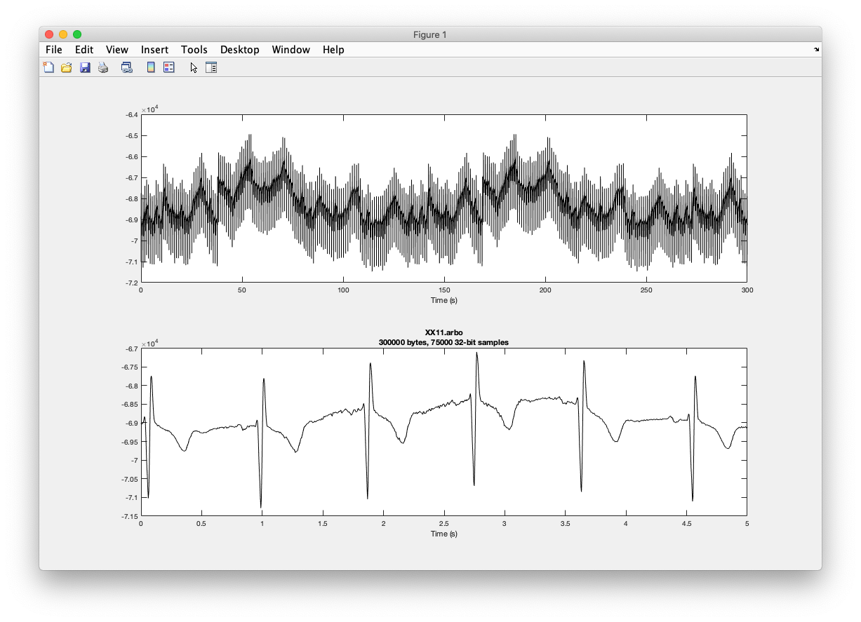
    I've basically been playing with using different channels for RLD_SENS and nothing seems to bring the signal around 0 (see image below), but this could just be that my electrodes are weak. In my real application, IN1P/N are coming from skull screws (i.e. neural) and IN2P/N from cardiac leads, IN3P/N from an EMG wire. Firstly, it's unclear if those will act in harmony to create a useful bias? Secondly, if I did use the BIAS, it's unclear what type of interface with the body I should use (large and diffuse surface/electrode under the skin? a wire into muscle?).

  • Hi Matt,

    This is far from a "typical" application. Very interesting though, it is for a horse? 

    Are the cardiac and EMG leads attached to the skin? If so, I would use one or both of those. If you haven't tried it yet, I suggest trying with both positive electrodes. 

    I don't see anything wrong with your register configuration. 

    Most of the noise is coming from the lights coupling onto the skin. I would actually not expect the RLD measurement to zero out, but instead be a 60Hz inverse sine wave with respect to the power grid. The RLD is simply an opamp taking the signal derived from the electrodes and injecting the inverse back onto the patient completing the loop. If your skin electrodes are not secure this will cause a variable impedance in the signal chain and the loop will continue to change as it attempts to compensate for this changing impedance. 

    The ECG reading looks very clean to me. 

  • Squirrels! I guess without sticking into muscle I don't have a feel for my resolution I'm just wondering why the current implementation isn't zero-centered? My read was that the bias electrode should remove the bias? The signal I showed were crappy stick-on pads, the real leads will be intramuscular, which could be the issue.

    Is there a good bench test for the bias you might suggest just to make sure I'm not obfuscating my integers or something?

    Thanks!

  • Oh wow. I suppose shaving them and sticking on electrodes isn't really viable then. 

    What is the scale of your y-axis? What gain are you using? The device is typical 500uV of offset, multiple this by gain you would have a typical "perfect connection" dc offset number. However if there is a mismatch in impedance for the electrode connections then this will look like an offset as well. 

    Unfortunately I don't really have a good bench test to suggest for you. RLD is simple in theory buy oftentimes tricky to implement correctly since it depends on so many factors such as environment, PCB design, electrode connection etc.

  • I've been using different gains, the signal scales as expected. In my experience, this just takes some bench tuning, just making sure I'm walking in with as much confidence as possible. I'll reply back once we get in-vivo data! Thanks very much, the support makes me happy to keep working with the ADS.

  • I understand. Good luck! Very interested to hear how this goes and my pleasure.