This thread has been locked.

If you have a related question, please click the "Ask a related question" button in the top right corner. The newly created question will be automatically linked to this question.

ADS1256: ADS1256 DRDY not going low

Part Number: ADS1256

Hello,

I'm trying to communicate with the ADS1256 but I can't get DRDY low. The SPI port is working ok, as I have tryed it and see ok signals on the osciloscope. I'm working with SPI mode 1 and a CLK signal of 1Mhz approx. I attach the code I'm using. It's based on an answer provided in this forum to see if you are communicating with de ADC ( e2e.ti.com/.../154300 )

SPI_MasterSSLow(spiMasterE.port,PIN4_bm);  // Set CS to low
_delay_us(0.5); // In datasheet it's T3 = 0, but everyone recommends introducing a short delay
SPI_MasterTransceiveByte(&spiMasterE,ADS_CMD_STANDBY); // Send Standby command
_delay_ms(200);   // Delay to see DRDY high
SPI_MasterTransceiveByte(&spiMasterE, ADS_CMD_WAKEUP);   // Send Wake-Up command
SPI_MasterTransceiveByte(&spiMasterE, ADS_CMD_SDATAC);   // Send SDATAC
SPI_MasterTransceiveByte(&spiMasterE, 0x53);             // Send WREG DRATE
SPI_MasterTransceiveByte(&spiMasterE, 0);                // Send to write only 1 byte
SPI_MasterTransceiveByte(&spiMasterE, ADS_DR_30000);     // Send Data Rate 30000
SPI_MasterTransceiveByte(&spiMasterE, ADS_CMD_SYNC);     // SYNC

  • Hi fabi,

    Welcome to the TI E2E forums!

    If you've powered the device, given it a master clock, and set the nRESET & nSYNC/nPDWN GPIO pins correctly, you ought to see /DRDY pulsing, without having to send any commands to the ADC.

    I would check to make sure /DRDY is working first (without talking to the device over SPI), and then in your code I would recommend toggling /CS between commands (to help ensure that the micro and ADC remain in-sync) and also add a WAKEUP command after the SYNC command to synchronize the device.

  • Hi Chris,

    I power the ADC and it has an external crystal of 7,68MHz as master clock. I've measured the following pins to see if it's correctly powered:

    • AVDD = 4.5V
    • VREFP = 1.4V
    • AINCOM = 1.5V
    • DVDD = 3.3V
    • nSYNC = nRESET = 3.3V
    • AGND = VREFN = DGND = 0V

    Without starting any communication with SPI and only powering the ADC, I still get nDRDY high all the time. Reviewing the circuit and PCB design, I realized that the 3 ADS1256 on the board have the nDRDY pin connected to the same node, making all the 3 nDRDY pins short-circuited between the 3 ADC. I suspect this might be the problem on why we are getting nDRDY high all the time, is it correct to think this?

    Thank you very much,

  • Hi fabi,

    The pin voltages are mostly fine... The only issue is that AVDD is lover than the minimum 4.75V per datasheet specifications. It is likely that the ADC will still operate with a 4.5V analog supply, but performance may not be up to datasheet values.

    Tying all of the /DRDY pins together could certainly be the cause of the problem. I don't know if you plan to operate all ADCs synchronously, but if you do then you'd probably okay monitoring just one /DRDY signal and reading the data from all three ADCs.

  • Hi Chris,

    I've seperated all the nDRDY pins but I'm still getting nDRDY high on power-up. I don't know what else might be causing this problem.... All the ADC pins seem to be ok connected, no short-circuit or anything else that might be setting this nDRDY pin high....

    Is there anything else I can try?

    Thank you

  • Hi fabi,

    Have you probed the crystal or clock input (on the XTAL1/CLKIN pin) to ensure that the ADS1256 is getting a clock signal?

    Also, if you're able to share a schematic (you can send it to pa_deltasigma_app@ti.com if you prefer not to post it here) it might help me troubleshoot the issue.

    Best regards,
    Chris


  • Hello Chris,

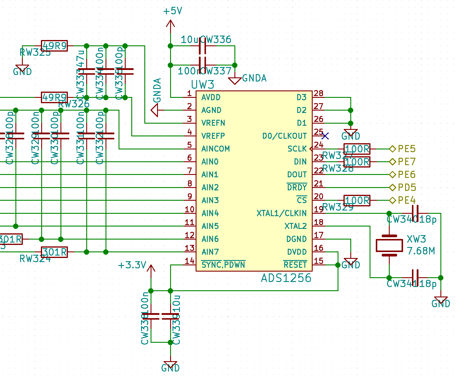
    Attached is the schematic of the circuit we're using. I've tried measuring the external clock but I've had no luck. What I'm doing to measure it is: power on de board and measure with an oscilloscope between GND and one of the pins of the crystal, all with the probe on X100. 

    PE5, PE6, PE7, PE4 and PD5 are connected to the corresponding pins of an Atxmega256A3U.

  • Hi fabi,

    Are GNDA and GND connected together anywhere on your board?

    These pins should connect to the same ground potential, preferably the same ground plane (See [FAQ] PCB Layout Guidelines and Grounding Recommendations for High-Resolution ADCs).

  • Hi Chris,

    Looking carefully at the board I see that I have 2 GND planes (one analogic and one digital) and they're only connected between them with a capacitor. I've just connected the AGND and DGND pins of the ADS1256 together and I'm getting a pulse train on nDRDY.

    Thank you so much for your help.