This thread has been locked.

If you have a related question, please click the "Ask a related question" button in the top right corner. The newly created question will be automatically linked to this question.

ADC08D500: Question about the Configuration in DES mode

Part Number: ADC08D500

Hi team,

My customer is testing our ADC08D500 in a DSO project. And we met below issue:

1. When set the device to normal dual channel mode, the device works well and the DCLK pin output clk signal is present. The register configuration is as below:

write 0x7fff to REG 0xd

write 0x07ff to REG 0xe

2. When set the device to DES mode, the issue is that the DCLK pin output clk signal is gone after configuration. The register configuration is as below:

when select CH1 as input: write 0xffff to REG 0xd; write 0x07ff to REG 0xe

when select CH2 as  input: write 0xffff to REG 0xd; write 0x87ff to REG 0xe

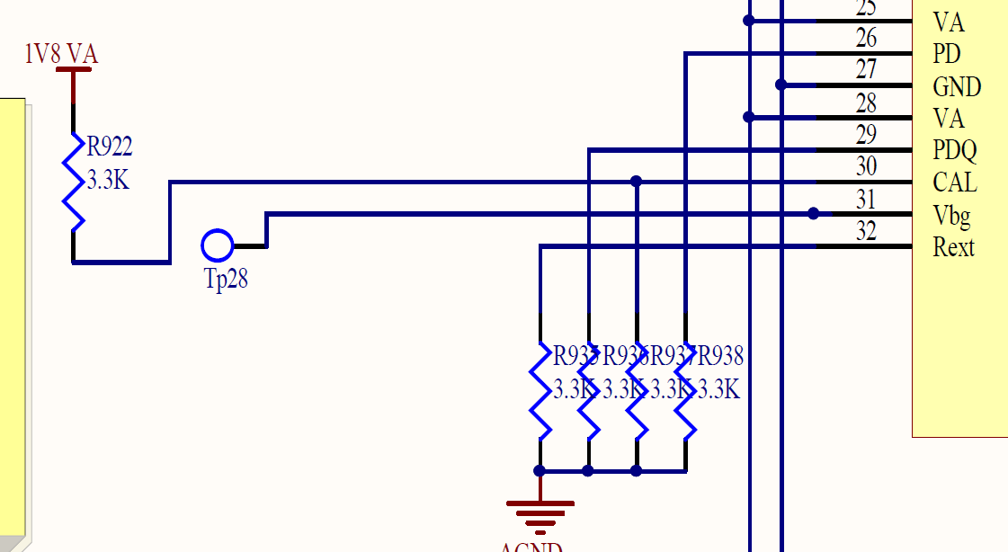
I have checked the schematic, the key pins connection are:

DCLK_RST: to GND,

PD: to GND

PDQ: to GND

FSR/ECE: floating

The schematic seems OK. So can you help advice why the device is abnormal in DES mode? Is there any other register needs to be configured or any other step needs to be done before enabling DES mode? Thanks.

Best regards,

Wayne

  • Hi Wayne,

    On page 27 there is a note see below. Reg  0xD needs to be programmed with the default first, 0x3FFF. Is this being done first?

    Regards,

    Rob

  • Hi Rob,

    Customer has followed the rules. In the code of power up initialization, customer has set all the 8 REGs to their default value. And then they will write to the desired REG according to the mode requirement.

    The strange thing is:

    step1: customer configures ADC to normal dual channel mode. The DCLK has output.

    step 2: customer change REG configuration to DES mode. The DCLK stops output.

    step3: customer change REG configuration back to normal dual channel mode. The DCLK shows up again.

    So it seems that the change of REG configuration did works but there's something else wrong during DES mode. One thing I noticed is that customer uses the FPGA to generate the input clk for ADC and the ADC's input clk from the FPGA has poor quality whose duty cycle is not that stable.

    I suspect in step 2, the DCLK stopping output is related to the poor quality input clk of ADC. But what makes me confused is that in step 1 and step3, the DCLK is normal while the input clk is the same as step 2. 

    So I want to check with you that if the input clk to ADC08D500 has a unstable duty cycle, will it cause DCLK stops output in DES mode? Thanks.

    Best regards,

    Wayne

  • Hi Wayne,

    I did some digging...see below.

    Thank you,

    Rob

    The Gen2 8-bit GSPS devices have a bug in the DES clock generation circuitry. The bug causes the DES clocking to lock up if calibration is run while DES mode is selected.

    This was fixed on ADC08D1X20 and later generations.


    See this on page 37 of the datasheet:


    The proper configuration sequence is:

    Power on and stable

    • Clock on and stable

    • Configure device as needed, except with DES disabled

    • Calibrate

    • Enable DES

    Also make sure the input clock is differential and is AC-coupled. DC-coupling the clock will cause problems with clock operation in general, and especially if the duty cycle correction feature is enabled (enabled by default).


  • Hi Rob.

    Thanks for the explaination. But to save FPGA I/O port, customer didn't use a I/O pin to control ADC's CAL pin. So they cannot trigger a On-Command Calibration at any time. Instead, customer leaves room for a pull up resistor and a pull down resistor on CAL pin as below picture.

    My understanding for the CAL pin from the datasheet is: 

    Condition 1: customer pulls CAL pin high through a pull up resistor. In this condition, the power on calibration process will be not be performed because CAL pin is high at power up. The On-Command Calibration won't be performed neither because customer cannot control CAL pin.

    Condition 2: customer pulls CAL pin low throught a pull down resistor. In this condition, the power on calibration process will be performed at power up while the On-Command Calibration still cannot perform.

    So my question is:

    1. If my understanding on condition 1 and condition  2 are correct.

    2, In condition 1, the ADC won't do calibration at all. Is this acceptable? 

    3. In condition 2, the ADC will do calibration only once at power up. Is this acceptable?

    4. No matter in condition 1 or 2, the ADC won't do calibration during DES mode. So I am afraid the bug is not the reason for customer's phenomenon.

    4. In your advised proper configuration sequence, is the 'calibration' before 'Enable DES' a must-do thing?

    Thanks.

    Best regards,
    Wayne

  • Hi Wayne,

    Can you please confirm what the sampling rate of the ADC is and if the clock is directly connected to the ADC, DC coupled?

    If you have a portion of the schematic to confirm this that would help.

    Regards,

    Rob