This thread has been locked.

If you have a related question, please click the "Ask a related question" button in the top right corner. The newly created question will be automatically linked to this question.

ADS1115: Comparator function

Part Number: ADS1115

Hello,

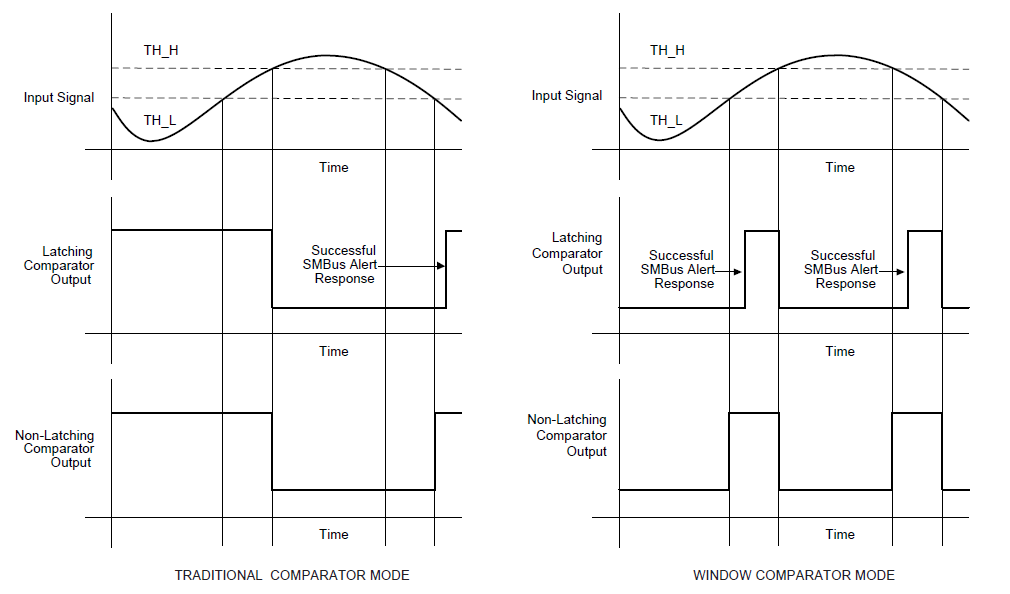
Our customer need to use the Altert Pin as  comparator function, but he didn't get the waveform of Figure 28, his configuration is as following:

1.Config  registers:  high Byte 0x42 ,low Byte 0xF8;

 2. Setting the threshold value:   LowThresholdValue 1800,HighThresholdValue 2500

3. ADS1115 Conversion data changes  between  1200 and 3000,but the output ALERT is always low, so how to get the Figure 28 waveform:

I read the datasheet,  it describes that to use the comparator function , the Hi_thresh register value must always be greater than the Lo_thresh register value.

Could you please help to analyze?  

Best regards

Kailyn

  • Kailyn,

    If the customer is able to get data out of the device, at least that's a good sign. 

    There are only two things that I can think of offhand. First, I'd like the customer to read back the threshold registers. If they are set to the default settings, then it's possible that they have an error in the write of the registers. They should verify both threshold registers. They could also set the high register to 0000h and the low register to 7FFF. This would cause the ALERT/RDY to trigger at each conversion.

    The second thing that they should check is the connections to the ALERT/RDY pin. This pin does not have an active output and requires a pullup resistor (similar to SDA and SCL).

    Have the customer check these things and post back with their response.

    Joseph Wu

  • Hello Joseph,

    Thank you very much, and I have confirmed with our customer, he has been pulled up the Alert pin, and the  high register  configured 2500 while  low register is 1800.

    Do you have any other suggestions?

    Best regards

    Kailyn

  • Kailyn,

    I'm sorry I didn't post back on this, but I was busy on another project last week. 

    With my last post, I did mention that they should verify the write of the registers by reading back from the device. Did they do this? It's important that they verify the I2C communication with the device.

    One thing that would be helpful would be to use an oscilloscope or logic analyzer just to check the I2C communication. It's should be easy to see the two lines and be able to see the data directly. I just want to verify that they chose the correct registers in the write. 

    I also mentioned in the previous post that they should set the threshold registers to try to trigger the threshold at each conversion. Did they try this? Did the ALERT/RDY trigger at all for any conversion?

    Other than that, can they share a schematic? Perhaps there's something mis-connected in the schematic.

    Joseph Wu

  • Kailyn,

    I haven't heard from you for a while, so I thought I'd check on this thread. As I mentioned in the last post, I did suggest some things to try debugging threshold setting.

    For now, I'll close this thread. If your customer still has problems with this issue, post back with some results and we continue working on it.

    Joseph Wu