This thread has been locked.

If you have a related question, please click the "Ask a related question" button in the top right corner. The newly created question will be automatically linked to this question.

ADS1158: Lower than expected samples per second

Part Number: ADS1158

I've got a few ADS1158s on a custom board, and they're mostly working. Due to a pin-mapping error, the only way I can read data from them utilizing the channel read data command in Auto-scan mode. 

I've configured the ADC to be as fast as possible, by setting DLY = 000 and DRATE to 11. According the datasheets table, this configuration should give me 23,739 samples / sec.

 I thought that the limiting factor of the data read/transfer rate would just be the speed of the SPI bus. However, the MCU is requesting about 12,500 samples per second and 75% (about 8,400) of the returned data are not marked as "new" data (bit #7 of the first returned byte). So it seems the ADC is reading in data much slower than expected.

I'm initializing the ADS1158 to sample as fast as possible, and am reading in all configuration registers to double-check that they're properly configured. I've also measured the external oscillator frequency to verify that they're outputting the proper frequency of 32Khz - which they are.  

I've poured over the datasheet, trying to figure out if I'm missing something but I haven't been able to find anything. What could be the problem here? Is there something I'm missing?

  • Hi John,

    I assume you are using all 16 single-ended inputs on each ADS1158?

    As stated in the datasheet, the 23kSPS/ch comment is when using 1x channel. As you can see from the image below, when using multiple channels, this number must be scaled by that factor.

    So, if you are using all 16 channels, then the effective data rate per channel is 23kSPS / 16 ch = 1.43 kSPS/ch. So this is approximately the data rate at which you would expect DRDY to pulse for new data.

    Let me know if that is clear.

    -Bryan

  • Sorry I wasn't clear, I'm sampling all 16 channels at once which should give me a rate of 23739/16 = 1.43kSPS/ch.

    But I'm only getting ~213SPS/ch. So the ADC seems to be sampling about 6 times slower than expected.

  • Hi John,

    Can you post your register settings and a scope capture of the digital lines? That might help diagnose the issue.

    And you are using a 32 kHz crystal oscillator, not an external clock, correct?

    -Bryan

  • Hi Bryan,

    Thanks for the help! I'm using an external oscillator. I've measured their start-up times and wait until they've properly stabilized until I initialize the ADCs. The register settings are as follows:

    I read out each of these after they're configured to double check that they're properly configured.

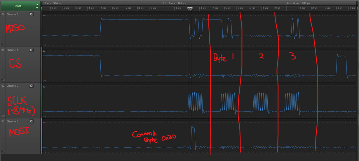
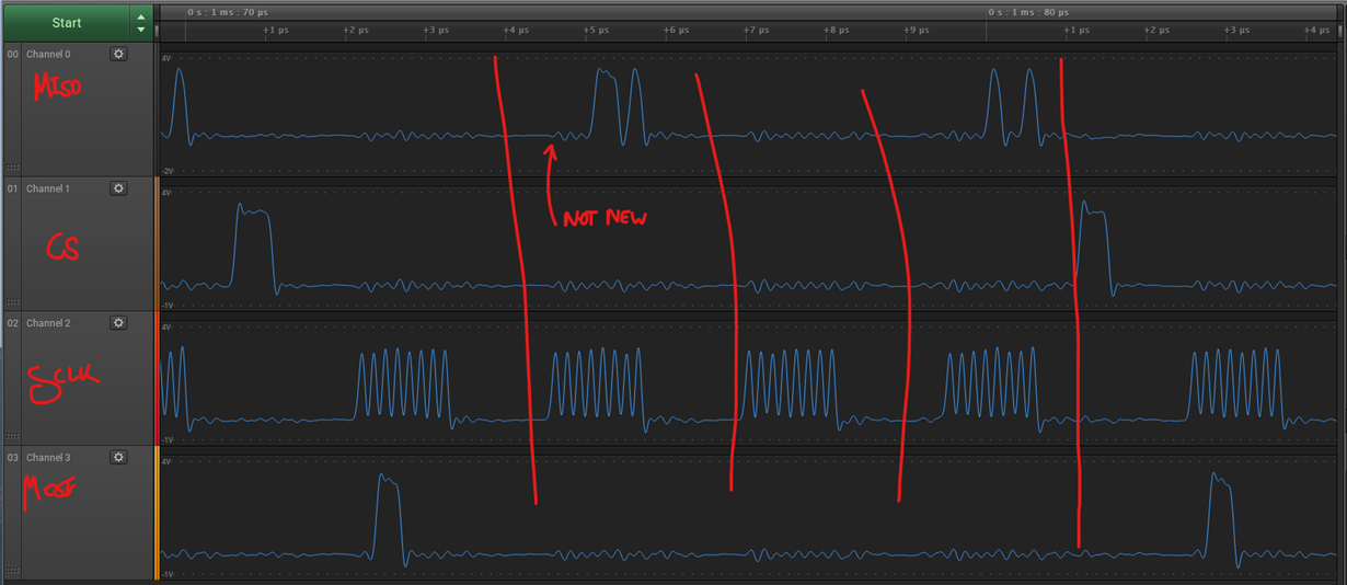
    So far, I haven't been able to find any issues on the SPI bus:

    SPI transmission with new data:

    However, most command bytes are answered with the data new bit being zero:

    Do you have any ideas for further debugging?

  • HI John,

    The scope shots didn't seem to come through in your last post.

    You have CONFIG1 = 0 111 00 11. Bits [6:4] = 111, which sets the delay to 384 us. This setting changes the effective data rate to 2,347 SPS. This is shown in Table 14 on page 18 of the ADS1158 datasheet.

    This 2,437 SPS value is for 1x channel, so if you are scanning through 16 channels, then your effective data rate is 143 SPS/Ch. Your notes indicate that DLY should be 000b, and DRATE should equal 00b, which is not reflected in the actual register definition. But if you are using CONFIG1 = 01110011b, I can imagine you would get data out much slower than you are expecting.

    -Bryan

  • Hi Bryan,

    Sorry that shot was from an older version of my firmware, the correct values are:

    These are the configurations I'm using when I'm getting 4.1KSPS total, when I should be getting ~23.7KSPS. 

    I re-attached the scope shots:

  • Hi John,

    Can you provide a schematic of your system?

    Also, can you use the digital inputs on the logic analyzer to sample the SPI faster and hopefully provide more accurate signal levels? It would help to see at least 2x consecutive conversions, to understand the timing gap between them.

    Hopefully this will help narrow down the issue.

    -Bryan

  • Hi Bryan,

    Could we continue this conversation over email? I'll get everything back the logic analyzer in digital mode ASAP.

    Thanks,

    John

  • Hi John,

    I requested a connection with you via E2E so we can share any sensitive information in a non-public setting.

    -Bryan

  • Hi John,

    Just wanted to follow up with question since it was remedied offline. The issue was clarity on how the output buffer / shift register works on the ADS1158. In auto-scan mode, the ADC only takes 1x conversion per channel, then immediately moves on to the next channel. So if you converted Ch1, Ch1 data would be available in the shift register on the SDI pin until the next conversion has completed on Ch2. Once Ch2 data is converted, this overwrites the previous channel data, so reading out data provides the converted data from Ch2. At this point, the data from Ch1 is no longer available to you, and there is no buffer / FIFO to read that back. You would then have to wait for the auto-scan sequence to wrap back around until Ch1 again. And again, this process repeats indefinitely until you interrupt the ADC operation.

    Therefore, our recommendation is to monitor DRDY since this indicates when channel data is ready to be clocked out. The DRDY pulses should appear on the DRDY pin at approximately a frequency of the data rate / # of channels. If this is not the case, there might be a supply or clocking issue. If this is correct, then the ADC is converting properly and there needs to be firmware to check for DRDY pulses and then issue the correct number of SCLKs to clock out data.

    -Bryan