This thread has been locked.

If you have a related question, please click the "Ask a related question" button in the top right corner. The newly created question will be automatically linked to this question.

ADS1298ECGFE-PDK: ADS1298ECGFE-PDK

Part Number: ADS1298ECGFE-PDK
Other Parts Discussed in Thread: ADS1293EVM, , ADS1298, ADS1293, ADS1299

I have unsuccessfully tried to use an ADS1293EVM with a 5 lead sensor cable to detect fetal heart rate during pregnancy. I am able to detect the mother's heart rate but not the baby's.

1 - Can someone tell me if I would gain an advantage in my project, by using the ADS1298ECGFE-PDK, Performance Demonstration Kit?

I can see that this board would allow me to use a 10 lead/sensor DB15 cable instead of the current 5 lead/sensor DB9, and hence should allow for more surface area to be covered during data capture. But I am not sure what other technical improvements in terms of noise reduction or sensitivity I would gain. I would appreciate any clarity that you can give me on this matter.

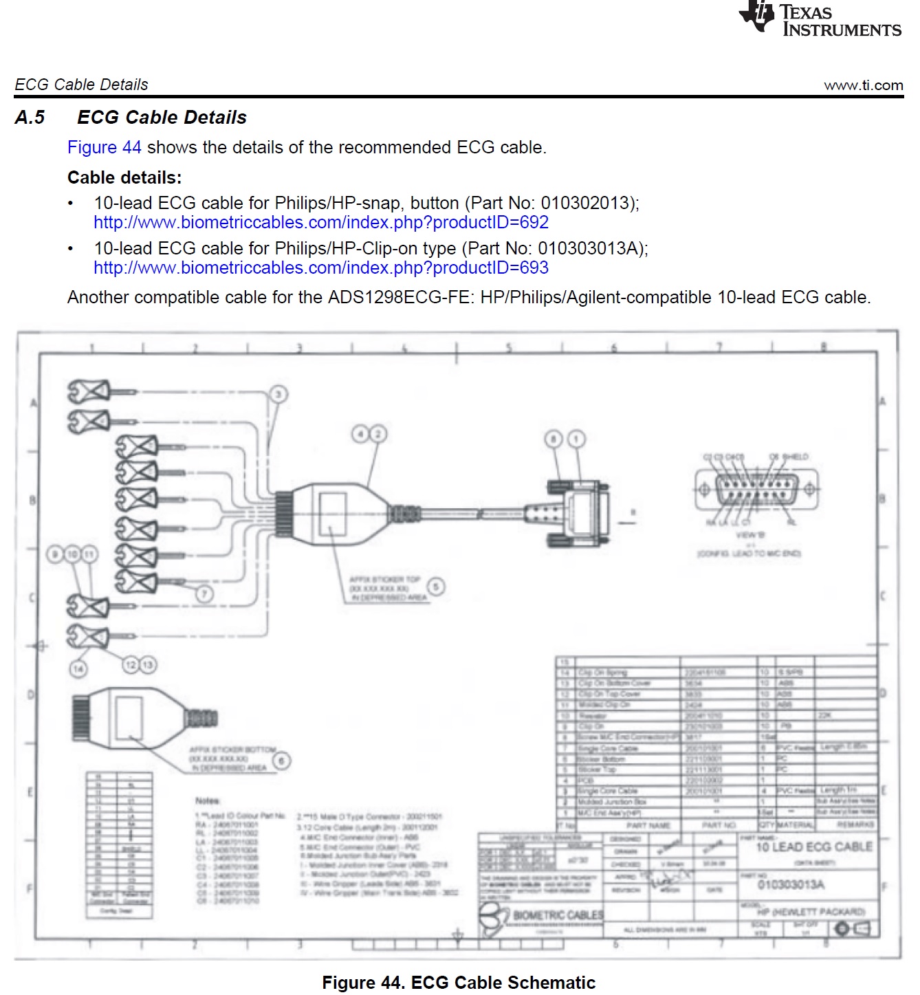
Also, on Page 46 of the datasheet for the ADS1298ECGFE-PDK, a diagram of the pin layout for a DB15 cable is give. However, as shown attached, the quality of the original document is very poor and I cannot see the writing on the page.

2 - Does anyone have a better quality copy or can direct me to where I can get the relevant info on that page?

The ADS1293EVM board that I currently have, is connected to a computer using a USB cable that does both transfer the captured data to the provided software and also powers up the board. I can see that the ADS1298ECGFE-PDK does power up with a 6V power supply. But I cannot see how the board is connected to the computer to transfer data. 

3 - Can you please let me know what I need in order to link this board to the computer and transfer the data as I capture it? 

I thank you in advance. I, unfortunately, don't have much technical knowledge on this and desperately need to fix my setup and finish my project. 

Arash 

  quality copy or the actual infomation on the page that I can access? 


  • Hi Arash,

    I'm sorry to hear that you're having trouble with your project, we've talked a lot about it over the past few months. I do not know much about specifically sensing the fetal heart rate, but I'm guessing that it involves significant digital filtering. It is possible that your hardware is fine with the ADS1293, switching to the ADS1298 would cost you some time to get familiar with the new software and such. 

    Can you share a little bit about what type of filtering you are implementing in post processing in order to try and pinpoint the fetal heart rate? Do you simply need to calculate the heart rate (beats/min) or are you trying to realize the signal? 

    Assuming that the fetal heart rate information is embedded in the ECG signal taken from the mother + fetus, can you subtract a generic ECG signal from what is recorded, theoretically leaving only the fetal heart signal? The heart rate for a fetus looks to be fairly high, ~150bpm so I would expect to see several small blips in the reading that correspond to the fetus. If you post screen shots of your current signal maybe I can help more.  

    As you can see in the BIOFAQ, the ADS1298 has slightly higher analog performance compared to the ADS1293 at the expense of consuming additional power. 

    After doing a little online searching, it looks like that particular cable is no longer sold, however comparable cables can be found online and the relevant information for those cables is on the manufacturer website. 

    The ADS1298 PDK is powered by a 6V power supply, a bench power supply and cables can also be used. The board transfer data to the PC via USB.  

    If you're just taking a few samples to verify performance of the ADS1298, you can use the provided GUI. 

  • Dear Alexander, 

    Many thank for your reply. The info is much appreciated... 

    I haven't used any filtering in the post-processing. The data point obtained from the software was extracted as a text file and then imported into MATLAB to draw the relevant plots. I have attached 3 copies of my data for your attention. 

    I would also appreciate if you could direct me towards any suitable filtering systems that you may feel would be relevant in my particular project. 

    As for the provided GUI for the ADS1298, is this not as comprehensive for the ADS1293EVM? My plan is to capture data in a similar fashion from 10 electrodes and then export into MATLAB for further analysis. Would the provided GUI be sufficient for such a task? 

    Many thanks 

    Arash 

  • Hi Arash,

    I would recommend working on the post-processing filtering. There is not a piece of hardware capable of doing this that I am aware of.

    Right now, your plotted waveform looks like fetal heart rate + ECG from mother + wandering baseline. 

    A beginning example of post processing would be to remove the wandering baseline, such that only fetal heart rate + ECG from mother is present. This could be accomplished by calculating a rolling average of how far a group of samples is from the baseline of 0, then adding/subtracting that DC value to the measurement.  This would result in the ECG from mother + fetal heart rate on a relatively stable DC value of 0. From here, it may be easier to identify in the waveform where the fetal heart rate information is and extract it. To me, the fetal heart rate looks looks like it is the small "bumps" in the waveform that appears to happen quite often, where I would not expect normal ECG from the mother to be. There are papers online that you may be able to find that discuss this further in depth. 

    The ADS1298 GUI would be capable of this task, however I believe it would yield very similar results that you are currently getting with the ADS1293. I do not think upgrading to the ADS1298 would solve this problem, it would simply give slightly clearer results. 

  • Hi Alex

    So you believe that my current signals do contain the desired fetal heart rate, but needs to be separated through post-processing? I have been looking up wandering baseline and a few other topics, but would you be able to direct me to any material regarding post-processing of such signals? any examples would be appreciated.

    As it stands, I am using 5 sensors and I was under the impression that having 10 in the case of the ADS1298, I would be able to get a much cleaner signal without the need for much post-processing. 

    Am I also right to assume that you think that even by upgrading to the more powerful ADS1298 board, my signals would still look more or less the same, and I still have to perform similar post-processing operations to extract the desired heart rates? 

    Kind regards

    Arash 


  • Hi Arash,

    It ultimately depends on where you are placing the electrodes, but if they are placed correctly for the application, then the signal should be present. Unfortunately I cannot since it is external to the forum, I simply suggest using a search engine. 

    The measurements are ultimately between two points when it reaches the PGA. I do not see how increasing the number of sensors would result in a cleaner signal. It would simply allow you to measure more points at the same time. The placement of the electrodes may be very critical for this application. So having extra electrodes may help you pinpoint these locations, but I believe you can also pinpoint these locations using the 5 electrodes available to you. 

    It is hard to quantify how much it would help here, but yes. There would be slightly less noise using the ADS1298. If you are going to upgrade, you may want to consider using the ADS1299 which has the best performance and extremely low input referred noise. This device is primarily intended for EEG measurements which are very small signals, perhaps similar to fetal ECG. 

  • Hi Alex, 

    Thank you for you information on the postprocessing and the possible improvements that I should make to my current setup. Hopefully, that should be enough to resolve the issue. 

    On the subject of choosing the ADS1298ECG-FE-PDK as a potential replacement hardware, this was due to the fact that I could simply purchase a box standard 10 lead cable that would directly connect ot the board through the DB15 connector. Having gone through the Datasheet for the ADS1299EEG-FE, I cannot see such an option. Could you please highlight what sort of connection I would be needing for that if I choose to use the board in the future? 

    Many thanks for your support. It is much appreciated. 

    Regards

    Arash 

  • Hi Arash,

    A manual connection would have to be made. I would recommend purchasing a DB15 connector to plug the ECG cable into, then fly-wiring & soldering to resistor pads on the input channels. This unfortunately would not be very robust, you would have to be very careful when moving the cable and board around. 

    Happy to help and good luck! 

  • Hi Alex, 

    I have started looking into postprocessing as we speak. But could you also please clarify the 3 points listed below.

    1 - My current lead cable is around 3 meters long. Do you think the length of the lead would have an adverse effect on the quality of the captured signal?

    2 - I currently use a small knitted conductive material for each electrode. To compare data, I have also used standard stick-on electrodes, but have had the same issues with the captured data. In terms of the electrode impedance, does the size of each electrode matter greatly? If I increase the size of the knitted material and in turn, the amount of skin contact, would that yield a sizable improvement? 

    3 - Do the ADS1293EVM or ADS1298FE boards have any other options extra to the existing filtration level on them, that I can change to improve the quality of the captured RAW data before moving to any post-processing?

    Thank you

    Arash  

  • Hi Arash,

    Is the cable shielded? If it is, then I do not see much of an issue. If not, the longer the cable, the more noise it will pick up. 

    This is tough to say. Theoretically, the larger the surface area the lower the resistance, but I cannot guarantee this will help. 

    I do not think there are placeholders for additional filters. You could fine tune the anti-aliasing filter and RLD filter. As these filters best performance vary from system to system.

  • Hi Alex, 

    Yes, the cable is shielded, but it does not have a dedicated pin connected to the earth. So to get around the problems, I used a ceramic ring, similar to what is used on standard data cables for other devices to dampen the noise. 

    Do you think I should invest in a cable that has an actual earth pin connected? 

    Thank you 

    Arash 

  • Hi Arash,

    I think you're referring to a ferrite bead. It's tough to say how effective this will be. All ferrite beads have their own impedance over frequency curves. If you have a datasheet for it, you may want to verify that it's impedance is high in the frequency range of the noise you want to suppress. Another good test would be to see how effective the measurement is with/without it. I believe the answers to these questions will help you decide if an earth pin is necessary. 

  • Hi Alex, 

    I have been working on the post-processor and have been refining some of the older signals I had recorded. As you can see from the first 2 photos attached, the fetal heart rate seems to finally become visible (highlighted in yellow), after the post-processing. The process should be refined further as there is room for improvements to be made.  

    I had to recently reinstall the software in order to take new readings. All settings are kept the same as the factory settings but I have encountered 2 problems which I would need some help on. 

    1-  Based on the 3rd attached photo, it seems that only channel 1 is taking any recordings out of the 3 available channels. Is there a solution that I can apply or a setting that I need to check in order to rectify this issue?

    2 - The recording time of the board has been lowered from the previous 60s to the current 20s. Could you please let me know where I would be able to alter this as I cannot locate this on the Data-sheet. 

    Many thanks for your help in advance

    Kind regards

    Arash

  • Hi Arash,

    That's great! Very exciting to see your progress here. 

    1. Honestly I'm not sure. Outside of making sure that the channel is powered on and recording in the registers GUI, I'm not sure what would have changed from a software re-install. Did anything change in terms of hardware? 

    2. Have you changed the sampling rate? This is limited by the numbers of samples being taken and how much data can be stored for a given measurement. So if you reduce the sampling rate, the time reading data should increase. 

  • Dear Alex, 

    For whatever reason, I continue the struggle with the ADS1293EVM board and keep failing to record a meaningful signal. In addition, the lack of any useful info or guidance on the Datasheet to explain all the available parameters that one can change on the software makes it practically impossible to navigate this.  

    Are there any suggested values for the parameters Output data rate (ODR), RMS , R1 & R2 rate, BW that one can use in a similar project to mine for fetal heart rate monitoring? 

    I do understand that you have already said that more channels don't necessarily mean better quality recorded signals, but it may give me a better chance of covering the right places on the body in order to detect one. So I was wondering if you could suggest any other boards that may be suitable for this project based on your previous experiences. 

    My own initial search took me to ADS1298ECGFE-PDK, which is an 8 channel board.

    Is there an option for a higher number of channels (more than 8) in the existing product range on offer? 

    Many thanks 

    Arash 

  • Hi Arash,

    I do not have any suggested values to provide nor do we produce an EVM with more than 8 channels. However, devices can be daisy-chained or cascaded together in order to create higher channel count designs.