This thread has been locked.

If you have a related question, please click the "Ask a related question" button in the top right corner. The newly created question will be automatically linked to this question.

ADC12D1800RFRB: The output signal looks like clipping even when input is low (50-100mV). How to adjust the scale?

Part Number: ADC12D1800RFRB

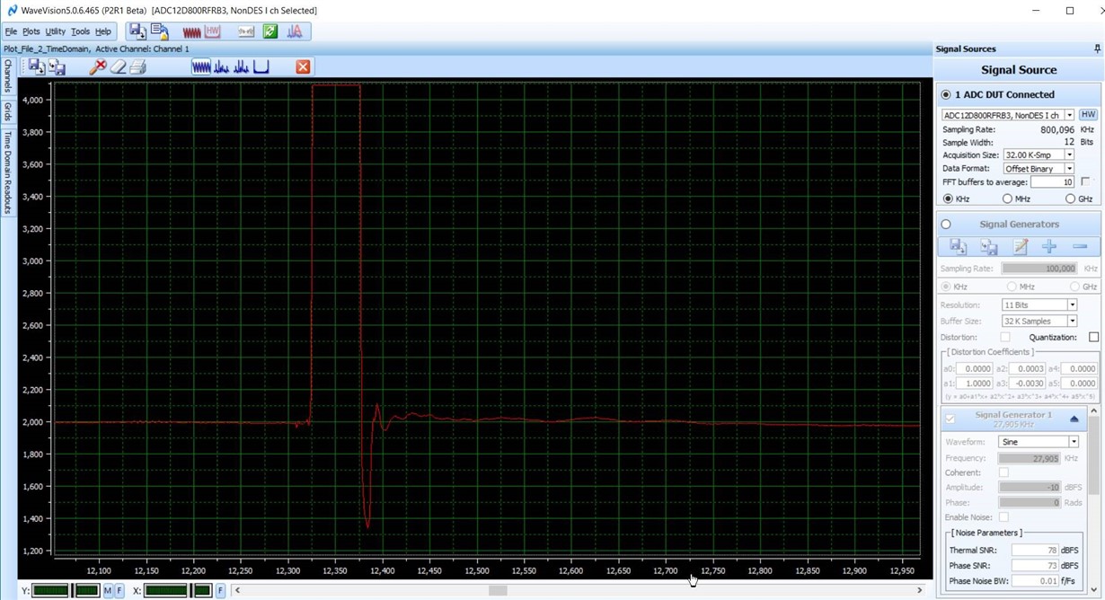
Hello, we are trying to use ADC subsystem ADC12D1800RFRB and I have a question related to the gain or scale of the output signal. I apply a 50-100mV input pulses from the generator, I also see the output pulses of correct width. But the amplitude of the pulses always seems to me like clipping. I've made a screenshot so please see attached below. The scale of the Y-axis looks like in bits counts and it always at maximum level. Are there any ways to change the scale/ gain , etc. I likely missed some settings or check/ uncheck some boxes.  Please advice.
  • Hi Michael,

    For you application, are you DC coupled to the ADC and EVM? Or AC coupled?

    There might be a common mode mis-match if you are applying a DC coupled signal.

    Regards,

    Rob

  • Good day Rob,

    I appreciate your quick response.

    I have being using AC coupling, basically I connected everything according to diagram in the manual.  I didn't see anything until I moved from differential input to single ended one, applied the signal to one positive input and shorted to GND with 50 Ohm the negative one. In this configuration I was able to see pulses, however they were clipping, that what I sent to you.

    The next experiment, I did installed the same WaveVision on another PC, connected and … bingo. I got the pulses I wanted to see. Coincidence? Maybe.  Summarising, I am using SE setup, pulses 100ns, 50mV, everything is working. Can you please explain the possible DC/AC coupling issue in more details. Can you also comment on why the differential setup didn't work?

    Thank you for your time,

    Michael S. 

  • Hi Michael,

    It might be better to understand your circuit before I can comment more, that way I can guide you better.

    Can you send me at the very least a block diagram on what this is being used to collect your pulsed data? The more details the better.

    Here are some high level questions and comments....

    what are you using for the signal pulse? Is this a function generator or an actual sensor?

    Is there an amplifier or any other circuitry between the output of the sensor and input of the ADC EVM analog inputs?

    This will give some better understanding on how you are connecting the input of the ADC differential or single-ended.

    On AC/DC coupling, the analog input of the ADC are floating at some DC value typically, in this case it is ~1.25V. If the output of the amplifier or sensor or circuit your have connected to those ADC inputs are floating at a different DC value then this can create problems.

    So unless you need to DC couple, it is best to use an AC coupling cap inbetween the two circuits...ie - sensor and ADC.

    Hope that helps.

    Regards,

    Rob