This thread has been locked.

If you have a related question, please click the "Ask a related question" button in the top right corner. The newly created question will be automatically linked to this question.

ADS8168EVM-PDK: ADS8168EVM-PDK

Part Number: ADS8168EVM-PDK
Other Parts Discussed in Thread: ADS8168

Hello there,

I want to do a project with ADS8168 EVM and stm32f407 discovery board. I will not use the PHI controller that comes with the kit.

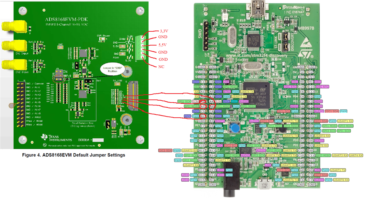
I add a photo of how to use it. I will connect with an external cable and connect external power supplies.

Can I use it as seen in this diagram?

If I can use it as in the diagram, can you share a sample code for stm32f4?

  • Hello Ilhan,

    Welcome to the TI E2E community!

    Yes, as long as the PHI board is not connected to the ADS8168EVM board, your connections look correct.

    SDO-0 -> MISO

    SCLK -> SPI-SCK

    SDI -> MOSI

    CSn -> To spi chip select, can be a timer out for precise control over sampling rate.

    Also, DVDD can be set to any voltage in the range from 2.35V to 5.5V, and should match the IO voltage for your host MCU.

    We do not have any sample code for the ADS8168.

    Regards,
    Keith Nicholas
    Precision ADC Applications

  • Hello Keith,

    Thanks for your answer.

    I set up the circuit.


    I connect CS and SDO pin with 10K (pull-up) resistor to 3V.

    I found another question that you answered for Markus before and followed the steps there.

    e2e.ti.com/.../768490

    I used the codes here.

    I want to share some measurement results

    External power terminal (P1)

    5.5V >> 5.32V (applied 5.32V adapter )
    3.3V >> 3V (applied 3V adapter)
    GND >> GND (All GND common)

    I measure 5.24V from 5.3V pin

    and other measurements;

    REFP 4.96V (external reference)
    DECAP 2.79V
    ADC-INM 0V >> GND
    ADC-INP 2.974V >> ADC-IN 2.974V

    RST >> 3.2V

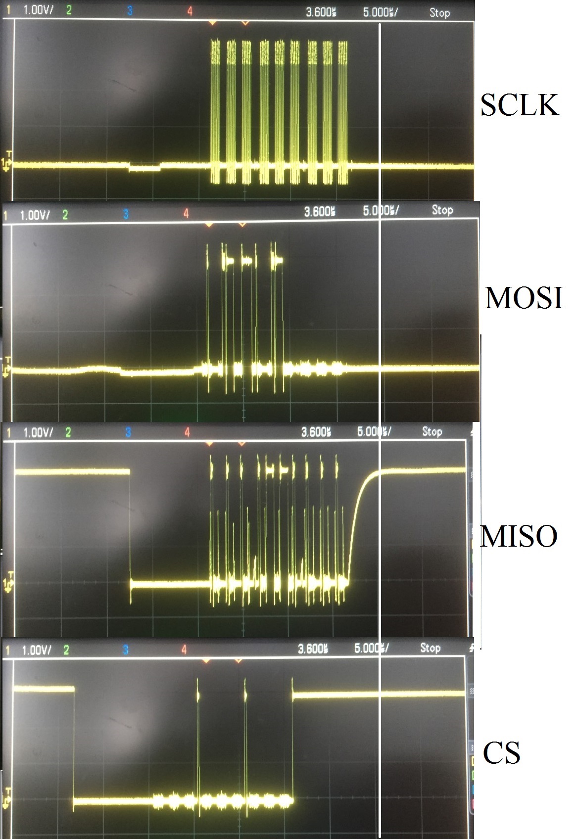
    Under all these conditions, my oscilloscope screenshot is as follows


    I think there is something wrong.I have similar problems. What can I do ?

    Thanks,

    Regards,

    ilhan Zengin

  • Hello Ilhan,

    The /CS determines the conversion time and overall data rate.  /CS must be held high for at least 660nS for the ADS8168.  I cannot tell from your waveforms if you are meeting this timing requirement.  However, the device is responding and providing data on the MISO line.

    Also, you have very long wires with a lot of noise pickup.  I suggest reducing your SCLK speed and overall timing to help with debug.

    Please provide a waveform capture with 1 SPI frame, so we can verify timing requirements shown in Figure 3 of the datasheet.

    Thanks!

    Regards,
    Keith