This thread has been locked.

If you have a related question, please click the "Ask a related question" button in the top right corner. The newly created question will be automatically linked to this question.

DAC161S997: 2-WIRE HART Communication solution

Part Number: DAC161S997
Other Parts Discussed in Thread: DAC8740H,

Hi Team,

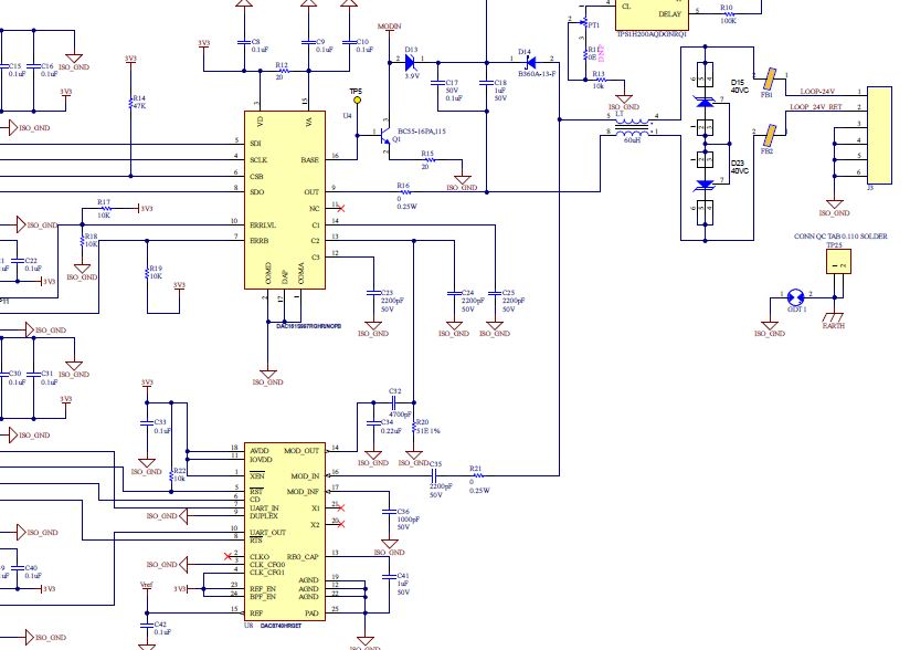
I am looking for EVM and reference schematic for 2-wire HART communication DAC161S997 DAC with DAC8740H(HART modulator).

Please share schematics and source code if any.

Note: I have attached draft schematic with the mentioned parts kindly review and let me know if any updates to be done.

Thanks,

Srinivas M

  • Hello Srinivas,

    Here is a link to the EVM design. The EVM design does not use the DAC8740H however it shows how & where the MODOUT pin of the modem needs to be connected. You will also find other reference designs for the DAC161S997 here.

    Can you attach a higher resolution version of your schematic design for review?  Unfortunately the image above is not clear enough.

    Regards,

    Reza

  • Hello Reza,

    Thanks for your reply.

    Hope is this image is clear, if not please share your email ID I will share the sch pdf.

    Request you to review and let me know if any modifications to be done.

    Thanks,

    Srinivas M

  • Hello Srinivas,

    This version is a little clearer however there are critical parts of the design that are not shown. The loop current path from 24V supply back to the NPN collector is missing. I suggest you send me a pdf version of the design to my email below for further review. Thanks.

    Regards

    Reza Abdullah

    g3reza@ti.com

  • Hello Srinivas,

    thanks for providing the schematic by email. Below are my comments.

    1. ERRLVL has 10k pull up/ down resistors. As such, an extra 330uA of current will always be consumed by the design. I suggest increasing the resistors to 100k to further reduce power consumption. I recommend the same on ERRB
    2. Is the net MODIN connected to any other part of the design?
    3. For HART injection, I recommend using the capacitor values in figure 20 of the datasheet. C1 = 390pF, C2=220nF, C3 = 1nF, C32 in your design will be 6.8nF and make C34 & R20 uninstalled.
    4. I see you have a switch between Loop-24V and Loop 24V. I have not tested a configuration like this before however so long as the switch turns on quickly enough, then I believe the circuit should startup correctly. I also see you have the option to install R8 for debug purposes. That is a good alternative to have.
    5. For the DAC8740H, you should replace C36 with 680pF instead, since you’re using the internal filter.

    We can either continue the discussion here or by email. If you want to continue with email, can you please close out this discussion thread? Thanks

    Regards

    Reza