This thread has been locked.

If you have a related question, please click the "Ask a related question" button in the top right corner. The newly created question will be automatically linked to this question.

ADS1115: Setup and questions about negative voltage reading and buffering

Part Number: ADS1115

Hi,

I am about to use the ADS1115 to sample the open circuit potential from electrochemical biosensors. The potentials will be in the range of +-1V and high input impedance is needed (10^13 Ohm).

I have been looking into how to sample a voltage range of +-1V but I have not figured it out. Some posts mention a level shifting OP-Amp to get voltage in the range between GND and VDD, but is this done with the differential mode or just a single ended reading? What is the recommended setup for this or am I out of luck reading negative voltages?

Regarding the input impedance, is it OK to just use an OP-Amp with a voltage follower setup to buffer the input or will this cause any problems?

Best regards,

Emil

  • Emil,


    Can you tell me a bit more about your system? How many sensors are you measuring? What model sensors are you using?

    If you're measuring an input signal that goes below ground, then you will need to level shift the voltage into the input range of the ADC. How you set up the ADC is dependent on how you level shift the voltage and what voltage output it will end up. I'd note that for the ADS1115, the ADC always runs differentially. Even though the input can be setup with the negative input grounded, the ADC still runs differentially, measuring AINP-AINN. If AINP is a handful of mV below ground or if there's a negative offset, the ADC will measure a negative voltage.

    With the high input impedance requirement, you'll need to use an op-amp buffer with the same. At this point, I'm not sure what op-amp would work for you, but again, I'd need more information about the sensor. I did find this kind of circuit, where you could use two input buffers that drive a fully differential amplifier:

    I wouldn't necessarily use any of these specific devices, but the topology could work for you. This is found in an apps circuit here:

    http://www.ti.com/lit/an/sbaa267a/sbaa267a.pdf

    You can read up on the circuit and a look it over. Regardless, post back with more information about your sensor and measurement details.


    Joseph Wu

  • Hi and thanks for the reply.

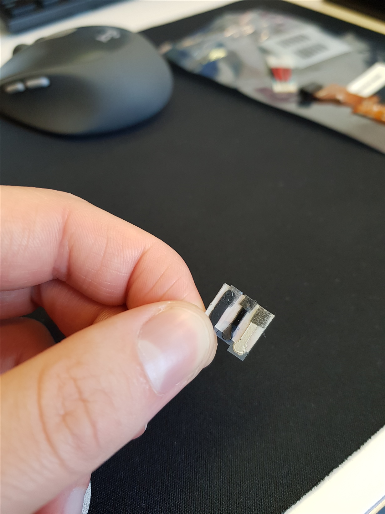
    My plan is to measure 5 single ended inputs (using up to four ADS1115 through I2C). I want to measure the open circuit potential from our own screen printed electrodes. See example of the cell below.

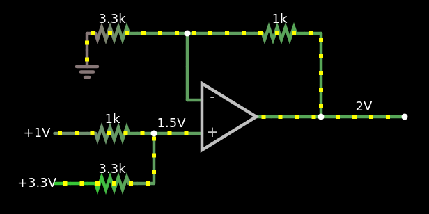
    The input signals will be between + - 1V. As the product is supposed to be wearable, the board space is limited which means single supply. My plan right now was to use a simple level shifter for the positive input of the ADC so that the +- 1V will be converted to 0-2V.

    The 3.3V seen here is the reference used to drive the whole circuit including ADC and u-C.

    Now in order to use the differential input of the ADS1115, one possibility would be to use another 1V reference on the negative input so that the full range of the ADS1115 is used, i.e the result is between -1 to 1 V.

    However, this might be a backwards solution since I need to add a 1V reference to the circuit and it might seem like I am just working around the initial problem. 

    As for the OP-amp, would it be sufficient to use an OP-amp with very high input impedance that matches my needs?

    Let me know if you need any more information or if I should tackle this problem from another angle.

  • Emil,

    I need a bit more information about your sensor. Are they resistive in nature? Do they require some active circuitry to drive? I just need to understand how you get the +/-1V signal to measure.

    I saw your amplifier circuit, but I wasn't sure why you needed a high impedance. If you are using the resistors to set the level, the low impedance looking into the resistor divider would be a problem.

    Joseph Wu

  • Emil,

    I haven't heard from you for a while, so I thought I'd check in and see if you've made any progress in your circuit. As I mentioned in my last post, I was concerned how the buffer may load the output of the sensor.

    I'll close this post for now, but if you have further questions, post back and we can continue discussing it.

    Joseph Wu