Hi,
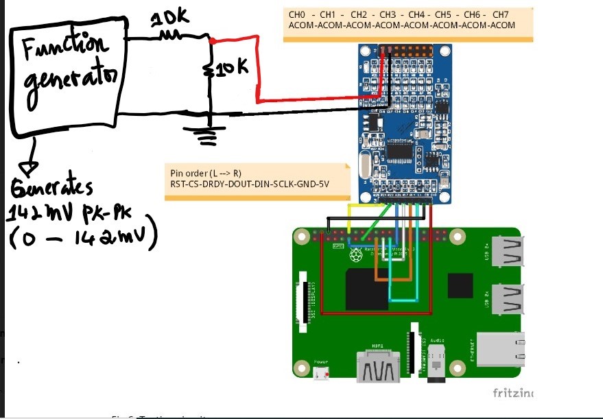
I generated a 2Hz 142mV pk-pk voltage (with min value = 0V and max value = 142mV) using a function generator (SWF-7000). I'm using a voltage divider with two 10k resistors to divide the signal by 2 so the the new signal should be 71mV pk-pk voltage (with min value = 0V and max value = 71mV). I'm sampling the 71mV pk-pk with an ADS1256 with a sampling rate of 500SPS using the differential mode and VREF = 2.5V. According to Table 8. Full-Scale Input Voltage vs PGA Setting found in the data sheet, I should be able to clearly see the signal using a PGA of 16, 32, or 64 since the signal amplitude is lower than 78.125 mV. However, whenever I was using those PGA settings (16,32,64) I kept getting maximum ADC value which 8388607 or 0x7FFFFF. And weirdly, I could clearly see (sample) the signal using the PGA = 1,2 or 4. For PGA = 8 I only partially saw the signal since some values were 8388607 or 0x7FFFFF. I'm using a Raspberry PI 4 to communicate with the ADS1256 and the SPI speed is 976000. I'm not sure what's the real meaning of the full-scale input voltage; it says I should be able to read a +/-78mV or (0 to 78mV) using a PGA = 64 but I can't read +/-71mV(0 to 71mV). I'm also not sure why I get an aliased signal when using Date Rate from 10SPS to 50SPS. 10SPS to 50SPS clearly satisfies Nyquist's sampling theorem since the frequency of the signal is only 2 Hz.
Thanks,


