This thread has been locked.

If you have a related question, please click the "Ask a related question" button in the top right corner. The newly created question will be automatically linked to this question.

ADS1115: Huge noise on ADC readings from a constant voltage source

Part Number: ADS1115

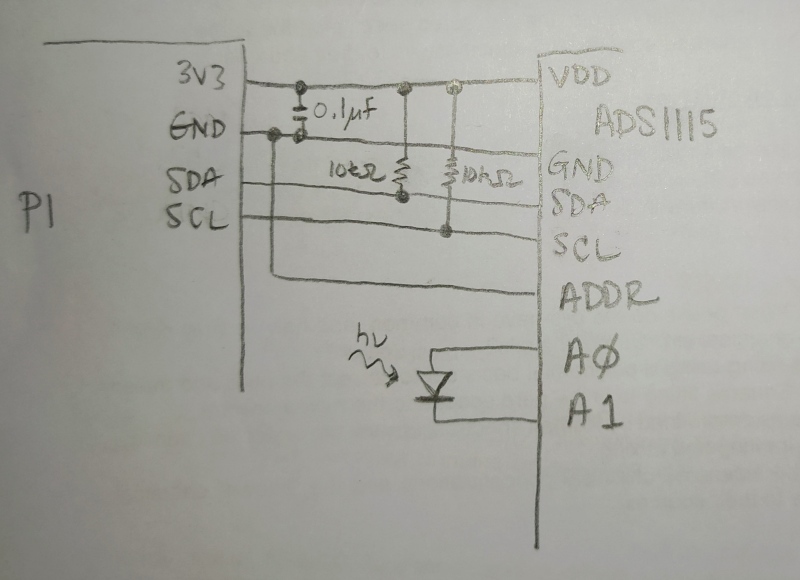
I'm currently trying to put together a circuit to measure voltages in the 0-1V range, diagram shown below (apologies for hand-drawing). The voltages are generated by light falling on an LED (which is directly wired to A0 and A1, as shown). Communication and power is handled by a Raspberry Pi.

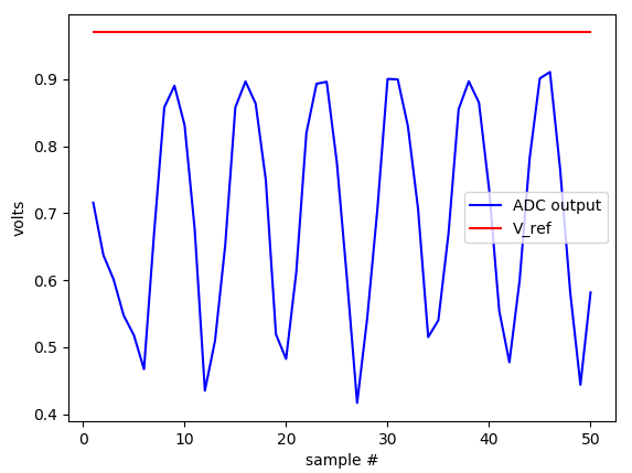
to test how things are working, I directly connected voltage from a DC power supply to A0 and A1, but got very unexpected results. With the ADC set at 860SPS, I occasionally get the voltage I am putting in (labeled as Vref in the plots below), but there are wild swings in the measured voltage:

Decreasing the SPS reduces the noise purely by averaging, so the measured voltage gets further and further from Vref (here it is as 128SPS):

I am wondering what could be the cause of this kind of behavior? Is it possible the ADC is damaged (for example it got too hot when I was soldering the board)? Or is it some deeper reason, for example there is a floating ground, since neither A0 or A1 are tied to the Pi's ground plane?

Many thanks in advance for any assistance.

  • Zachary,


    First, not all of the images in your post came through. Can you re-post them please? You can't use the copy/paste control keys in forum posts, and you need to use the insert image icon to make sure they're put in correctly.

    It is possible that because A1 isn't tied to ground, you're getting some aberrant readings. The input to the ADC (from A0, A1, or any of the inputs) must be within the input range of the ADC. This is between GND and VDD of the device. Also the input measurement should have a defined common-mode between the measurement and the ADC. From your drawing, the input appears floating. Can you connect A1 to ground to ensure that the sensor isn't floating?

    I would also ensure that the microprocessor and the device have a common ground and that the supplies are the same.

    If you're getting readings, I would find it unlikely that the device is damaged. You should be able to take some test reading to verify that the device is working.


    Joseph Wu

  • Thank you Joseph!

    I reposted the images.

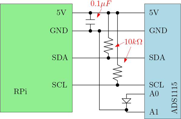
    After tying A1 directly to ground (previously I had tried tying it to ground with a 10kOhm resistor in series without success), the noise has thankfully (mostly) vanished (down to less than 1%, which I can live with).

  • Zachary,


    I'm glad that you were able to solve this problem. The ground connection is important to ensure that the input isn't floating and has a defined common-mode between the sensor and the device.

    As for the noise itself, this could be 60Hz line cycle noise coupling into the circuit. This could be 50Hz noise depending on where you are in the world. If you are measuring some sort of optical sensor and there is powered lighting, this might be coupling in through the sensor. It could also be coming in through the board ground, and disappears after the sensor ground and the device ground are connected.

    Regardless, I'm glad you got the schematic cleaned up. Let me know if you have any further questions.


    Joseph Wu

  • Thanks Joseph. I actually did run into another problem. The circuit, based on your help, now looks as follows, where I've hooked up the LED instead of the power supply:

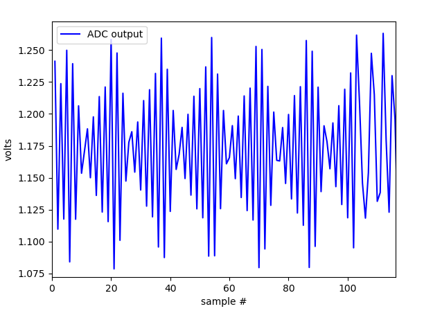
    When light falls on the LED, a voltage difference is generated between A0 and A1, which is being measured as a differential measurement. However, I have two problems. The first, is that the LED seems to be much noisier than the power supply, and that noise definitely has a well-defined frequency. Measurements are shown below, which look to me like an alias-sampled sine signal:

    Further, and very strangely, when I change the gain on the ADC, the ADC output doesn't change as expected. Going from gain 1 to gain 2, the ADC value only increases by something like 20-30%.

    The frequency structure of the noise seems to be too high frequency to be 50/60Hz noise. The data above was taken by repeatedly sampling in single shot mode at 860SPS with 0.005s between single shot measurements, so theoretically something like 200Hz. I'm wondering if it's something like stray capacitance inside of the diode setting up some kind of resonance?

    Any thoughts on how to improve the circuit or why the ADC gain is not functioning as expected?

  • Zachary,


    When you post the measurement can you send it with an excel file of the results. I would want the ADC raw data, and converted to a final value in volts or something else. Also, can you report the ADC configuration register? I want to know how the ADS1115 is set up.

    As for the noise that I see, this could still be something in your ambient surroundings causing the photodiode to get modulated. I don't think this is some sort of resonance in the photodiode. All lighting from CFL, LED, and even computer monitors will have some sort of periodic frequency. If you had this tested outside, the light should be more constant.

    As an alternate test you could set up a resistor voltage divider to and measure it with one of the other channels. This would give you a different measurement to look at that may be more consistent.

    One thing that you mentioned concerned me about your measurement. When you switch to gain of 2, the ADC values only increased by 20-30%. When you measure the diode, how strong is this voltage and what sort of output impedance does it have? As the gain changes, the ADC input impedance changes and with higher gains, the input impedance gets smaller and smaller. If you're at the 2.048V FSR and you change the gain to the 1.024V the input impedance of the ADC changes from 6MOhms to 3MOhms. If the diode measurement can't drive this, then you need some sort of buffer to drive the ADC.


    Joseph Wu

  • data_06012020.xlsx

    Please find the data attached.

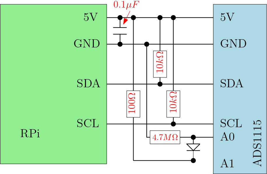
    I think you are exactly right about the voltage being determined by the impedance on the board, and this is what is causing the issue with gains. Following this application note: I was able to wire up the circuit as follows:

    when doing so, the gain works as expected, but the noise remains. I'm gathering the data from the ADS with some python code, and I added time-stamps to each data point to try and see how fast I'm *really* taking the data, including the program overhead. It seems to be a bit less than 100Hz in my current code (the code waits 0.005s between samples, so there's about another 0.005s in program overhead). The time-stamped data is what's in the attached file. I don't think it's room lights or any other environmental factor (apart from fluctuations in the power supply or ground being supplied to the ADC). I turned the lights off and placed the whole circuit including detector in a dark box with no change in the readings.

    Thanks again for your help and any suggestions are appreciated.

  • Zachary,


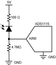
    I'm still unsure you have the circuit set up correctly. Tracing out your last basic schematic, you have something like this:

    Here, it looks like you're using a single ended measurement for the 4.7MOhm resistor. Do you have enough current biasing the photodiode, what kind of voltage do you expect? What current should you be seeing through the diode? In your schematic, it looks like the biasing current is way too low.

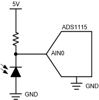
    I would have expected this kind of circuit, with more current potentially going through the diode:

    Still, there are a couple things to check. First, I'd make sure the ground between the sensor, the ADC and the microcontroller are the same. Also, I would make an alternate measurement, where you measure the supply or a voltage divider instead, just to make sure that the ADC is measuring correctly. Use a divider that uses resistors in the kOhms, not MOhms. Then come up with a definitive biasing for the diode. Again, I'm not sure you have the resistor/diode biasing correctly set up.


    Joseph Wu

  • Zachary,

    I haven't heard from you for a while, so I thought I'd check to see how you were coming along on your measurement. I mentioned a few things in my last post, but I wanted to make sure that you were setting up the circuit correctly and using the right bias for the photodiode for the measurement. 

    I'll close this post for now, but if you need more help on this device, post back and we can continue working on this circuit.

    Joseph Wu