This thread has been locked.

If you have a related question, please click the "Ask a related question" button in the top right corner. The newly created question will be automatically linked to this question.

ADS1115: Differential output not correct when measuring a 4-20 mA pH sensor using Raspberry pi

Part Number: ADS1115

Hi, 

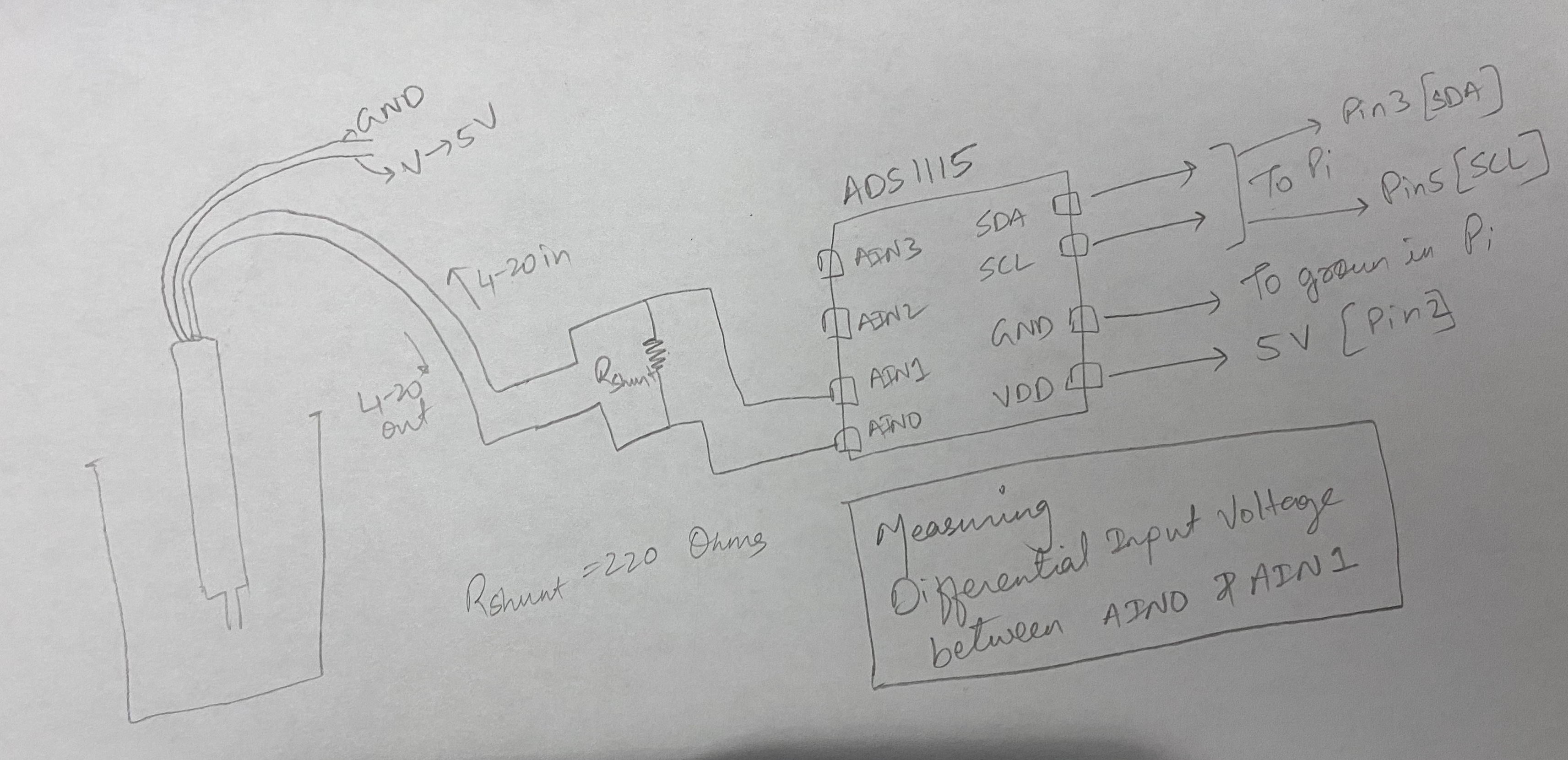
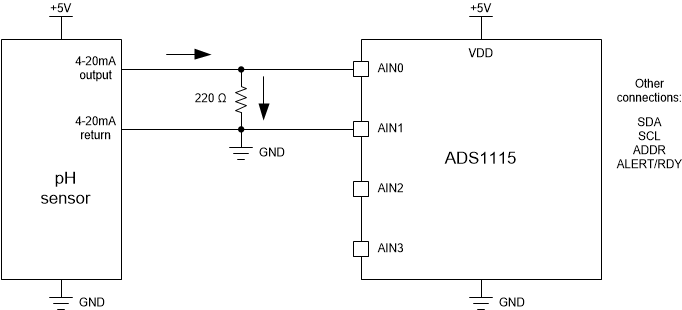
I am trying to measure pH using an Industrial 4-20 mA current loop sensor. I am using a shunt resistor to complete the loop and measure the voltage across the resistor using the ADS1115 and then read it through the Pi. 

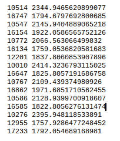
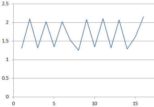
The reading I get using the ADS1115 is in the range of millivolts and I am assuming these are just garbage values. I tried measuring the differential voltage using a multimeter and I can get appropriate readings from the multimeter. I also measure the current using the multimeter and converted it to a voltage just to cross-check my value and it all makes sense. 

I am not sure what is going in the circuit. I don't have any components other than the shunt resistor. 

I did a quick test (Which helped me solve an issue in my previous project in which I was using a conductivity sensor): In that test, I tried measuring absolute voltage in each of the pins using a multimeter and I don't see any value, that is strange but as soon as I measure differential voltage I see the significant value. This is the question I am trying to find an answer so that it can help me develop the right circuit before I connect it to an ADC. 

Any information will help me identify the issue and get a solution. 

Thank you so much for your time. 

  • Kumar,


    I'll need a bit more information to help debug your measurement.

    First can you provide a circuit diagram? I need to know how you have it set up. I really haven't made any measurements for pH sensors, but I believe that the sensor is typically high impedance. I want to check that your 4-20mA converter isn't loading the pH sensor.

    Next, can you detail the communication with the device? I'd need to know how it's programmed and how you read data back. Specifically on the programming, what mode is it in, what data rate is being used, and what PGA setting is the device in. It would be best to show the entire configuration register setting. I'd want to know about how you're reading the data. Give the byte transactions to the device. I just want to ensure that you're reading the proper register with the I2C communications.

    When you are collecting data, what is the input at the time, what is output data are you expecting, and what is the data of what you are receiving from the ADC? It would be best to collect a series of something like 100 data from the ADC and post that back in a file (raw data from the ADC, not converted data to voltage or any other).

    It would be best if you got an oscilloscope to show the SDA and SCL waveforms. Communication with this device isn't so complicated and you can verify that the communication to the ADS1115 matches what you are programming into the raspberry pi.

    There's a lot to my reply post. Read through it carefully and post back with results and answers to my questions. I'm sure we can debug this.


    Joseph Wu

  • Hi Joseph, 

    Thank you for your reply. 

    I will post as much information as I could, please allow me today's time and I will post all the information you asked. 

    I don't have a datasheet to know the impedance of my sensor, but there might be a possibility of high impedance, is there any way I could check that using a multimeter?

    Secondly, I don't have an oscilloscope to check the waveforms. Apart from these two, I will post every detail I can. 

    Thank you 

    Kumar

  • Hi Joseph, 

    Replying to all the information you asked in your reply. 

    1. The circuit is attached in the post, let me know if you have any questions. The sensor outputs 4 - 20 mA directly, so I am not converting anything. 

    2. For the communication, I am attaching my python code which I am using to read the data, it is a test script but it will give you information on how I am reading the data. I am using PGA = 1 which is plus-minus 4.096V. For the data rate, I have let it in default, I don't make any changes for that. I have tried playing with it, but it didn't make any difference. For the mode, I use differential mode reading between AIN0 and AIN1. 

    3. I am collecting data every second, the differential input measured using a multimeter is constant at 1.604V at the time I took readings (I am attaching an excel sheet with some raw bit values and the voltage values which I got when I did a test run). I expect around the same reading which I get in my multimeter that is 1.604V. For the 4-20 mA sensor, I am using a shunt resistor to read the voltage drop between it which I can use later to calculate the current flowing through it. The value of the shunt resistance is 220 Ohms. 

    4. I don't have an oscilloscope to verify my communication from the ADC. But I have used the same ADC to read another 4-20 mA sensor, which is a conductivity sensor and it works perfectly with that. I was initially facing issue reading the Conductivity sensor as well, but later I figured that the voltage output from the pins does not lie in the range the ADC can accept, so I build a voltage divider circuit to reduce my voltage and then I was able to read the values perfectly. 

    A side note: You can see in the excel sheet that the voltage values that I am getting right now are somewhere around 2.8-2.9 V. Initially I was getting values in millivolts, but suddenly it started giving me these values, I didn't make any changes in the circuit. I am not sure why, after referring to some other forums for this issue, they have pointed out that it might be an issue related to the outputs which might be floating with respect to ground or power pins. I hope this information helps you understand a little bit more. Let me know if you think this might be an issue, or if I can do some more troubleshooting to confirm if this is the problem.

    I hope I have given all the information you asked for, please let me know if I have missed anything, I will be happy to share that as well. I am sure with your experience we can debug this issue.

    Thanks - Kumar

    Test_Script.docx

    Raw values from ADC.xlsx

  • Kumar,


    Thanks for the drawing of the setup.

    First, make sure that the sensor and the ADC have some sort of common ground. The input should not be floating with relation to the supply voltage. In order for the ADC to work properly the input voltages must be within the operating range of the ADC. This means that both AIN0 and AIN1 must be between GND and VDD.

    Looking at the setup, I would connect the ground of the sensor to the ground of the ADS1115 (or the RPi). Then, I would make sure that the return current from the sensor is returned to ground. In your setup, this would mean that AIN1 should be grounded. This way the current output of the sensor goes through Rshunt and then is sunk into the common ground. What is the model of the sensor you're using?

    I did look through the test script, but it's not enough to tell exactly how the device is set up. I also looked through the data, but there's nothing that looks too unusual. There's definitely some noise in it. The output average of the code is about 23136d, which translates to an output voltage of 2.892V. Note that your spreadsheet value for your voltage is a small amount off off. The conversion should be:

    Voltage = Output code * 4.096 / 2^15

    It seems that your voltage conversion is about 1.3% high.

    Regardless, make the change to the setup, connect the grounds and let me know if you get something different.


    Joseph Wu

  • Hi Joseph, 

    Thank you for your reply. I was waiting for it. 

    My sensor is already connected to the Ground of the Pi and the ADC is also connected to the same ground. 

    I tried connecting my AIN1 to the ground and measure the readings, it gives me constant values ( I am posting the values for your reference).

    -24 -3.0000915555284284
    -24 -3.0000915555284284
    -24 -3.0000915555284284
    -24 -3.0000915555284284
    -24 -3.0000915555284284
    -24 -3.0000915555284284
    -24 -3.0000915555284284
    -24 -3.0000915555284284

    And regarding the setup of the ADS1115, I am only changing the gain to 1, rest all the settings are in default mode. And regarding the sensor, it is not an off the shelf sensor, it is a sensor which I ordered from a supplier. I can give you the model number, but you won't find anything over the net about it. And about the voltage conversion, I am using the library function to get the voltage value, but it still might be incorrect, I will look into it. 

    1 point, I think when is kind of unusual is, I see different reading in the ADC every time for the same connection, for example in my above post, I was getting an output voltage of 2.892V average. Whereas now I am getting different values and it is fluctuating as well. I am posting some examples of the readings. And I have a multimeter connected simultaneously between both the pins and I get a constant reading of 1.767V. 

    I am literally stuck with no more options to try to resolve this issue, any more help from your end or recommendations will help us debug this issue. 

    Thank you - Kumar

  • Kumar,


    Part of the problem is that I'm not sure the device is correctly configured, and if the ADC is reading the voltage that you think it's reading. I'd want to make sure that the device is in the correct range and is measuring the correct analog inputs.

    Another problem is that I'm not sure how the pH sensor works. I'm not sure where the absolute voltages are for the connections, and what output voltage to really expect (exact voltage and if there's any AC component).

    Because of this, let's try two different experiments. First, let's make sure that the device is correctly configured, measuring a voltage, and reporting the correct data. The ADS1115 should be able to measure it's own supply, so start by disconnecting the inputs. Then connect AIN0 to +5V, connect AIN1 to GND. Set the input to AIN0-AIN1 and the input range to ±6.144V and then make the measurement. With any luck, the ADC value should be:

    Output code = (5V * 2^15)/(6.144V) = 26667d

    This should confirm that the ADC is making correct measurements. If you want, you could set up a resistor divider and check different ranges, but this should suffice for now.

    Then we want to look at the connections to the pH sensor. Using your diagram, I've redrawn it, so this is how I think the connections are made:

    What I don't know is, where is the voltage at AIN0 with respect to ground and where is the voltage at AIN1 with respect to ground. Note that the analog inputs should have an absolute voltage between VDD and GND. I would use the multimeter and measure the two voltages and make sure they are both in range.

    Earlier I had suggested that AIN1 should be connected to ground. This would ensure that AIN1 is ground and that the 4-20mA output would be sunk directly to ground (instead of going into the 4-20mA return). In that case, the connection looks like this:

    However, when you tied the AIN1 to ground, you say you get this constant reading:

    -24 -3.0000915555284284

    You basically get -3mV for a reading? I assume -24 is the ADC output code, and you're operating in the ±4.096V range. Is there any case where current is flowing out of the pH sensor?

    Lastly, for your last set of readings, I assume you've disconnected the AIN1 from GND again, you get the following readings (in decimal?):

    10514
    16747
    10547
    16154
    10772
    16134
    12201
    10010
    16647
    10767
    16862
    10586
    16585
    10276
    12955
    17233

    This average is about 13437 codes, which is approximately 1.68V. If your multimeter is 1.767V, at least this input is close. However, I'm not sure if your sensor is giving out a voltage that's oscillating, which might explain the ADC reading looking like this:

    At this point, I can't tell if the output voltage is really oscillating, or if it's constant. Again, I would use an oscilloscope just to look at this input voltage. I understand that you don't have one, but I would try to find one. Without the ability to look at the input signal, I'm not sure what the ADC is measuring.


    Joseph Wu

  • Hi Joseph, 

    I really really appreciate your so much detailed response to my issue. Thank you so much for that. 

    I will try everything you have suggested/recommended and get back with as much detail as I can to give us a better understanding.

    Thank you so much

    Kumar

  • Hi Joseph, 

    Please find my bulleted response below:

    1. I tried verifying the 5V reading with the steps you suggested, I am able to get 5.129V (27363-bit value) from the ADC whereas the actual reading using a multimeter is 5.14V. It is off by like 0.3%, but I think this is acceptable, please let me know your thoughts in this. 

    2. For checking the absolute voltages of the individual pins coming from the sensor: I think that is where the issue arises when I try to measure absolute voltage in any one pin and GND, the value I get in the multimeter is in the range of like 20-30 mV. It is the same for both the wires (4-20 mA IN and 4-20 mA OUT) coming from the sensor. And since there is no absolute voltage present, the ADC doesn't read any value. I think correct reasoning here is that both the wires have to be connected in order for the circuit to complete and that is when the current flows through the loop. That is why, when I connect both of them to the multimeter to get the voltage difference, I get the right reading.

    3. For your third question, that is: Is there any case where the current is flowing out of the pH sensor?. I don't think that the current is flowing out from the pH sensor, I think that when one end of the resistor is connected to ground, the current loop is not completed and hence there is no current flowing at all from the sensor. I think, the current loop has to complete itself for the current to flow. 

    4. For your last point, regarding the oscillating readings: I don't think that the values are oscillating in this case, but I would still try to get an oscilloscope from somewhere and try measuring the signal. But before that, I think the problem is what I describe in bullet number 2. If we are able to resolve that point, I think we will have a better understanding of the signal, whether the signal is oscillating or not. 


    Side note: I have contacted the supplier of the sensor to share some more information regarding the circuitry of the sensor and how it works electronically. Once I get that I will be sure to share it with you for better understanding.


    But I think the second bullet is where the problem is, please let me know if you can think of a solution to that. 

    Thank you so much - Kumar

  • Kumar,


    I think I'll wait to see what the supplier for the sensor says about the device. I'm still unsure what the output of this device should be. Originally based on your description, I thought this sensor would output a 4-20mA output that varied depending of the pH of the measurement. Because of this, the output current should get shunted to ground through a 200Ohm resistor that converts the current to a voltage that can be measured.
    However, the device seem to sink current into ground, or there's some sort of floating nature to the output of this measurement because the current gets returned to another pin, that doesn't seem to have a relation to ground.

    Once you get more information, let me know.

    Based on the measurement of the supply, I would imagine that the voltage is correct. I don't know if you're using using a precision meter, or if the error is within the error bounds, but it seems to me that 1.3% isn't large for a standard handheld meter.


    Joseph Wu

  • Sure Sir, 

    I will keep you updated with any information I receive from them. In the meantime, please let me know if there is anything else I can try to hopefully get a solution. 

    Thank you so much - Kumar

  • Kumar,

    I haven't heard from you for a while, so I thought I'd check on your application. As I mentioned in my previous posts, I think that the problem you're having is due to connections to this device's output and not being sure about how the current from the output 4-20mA converter is sunk.

    I'll close this post for now, but if you have problems getting this measurement or receive more information about the sensor output, post back and we can continue working on this.

    Joseph Wu