This thread has been locked.

If you have a related question, please click the "Ask a related question" button in the top right corner. The newly created question will be automatically linked to this question.

ADS1015: Problem on ADS1015 config register default value

Part Number: ADS1015

Hi Sir,

I'm using ATSAMD51 controller with ADs1015 interface.

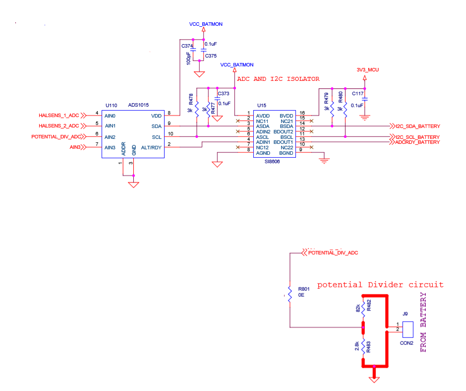
power supply  to ADS1015 is 5.5 V.  

Analog input channel 3 : 2.3V

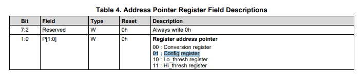
write config register setting value : e103 .  ( adc channel : 3, single ended inputs,+/- 6.144,128SPS, single mode, OS enable)

After reading the config register value : 8583 (default value).

Because of this default value, we can't able to measure the channel input  voltage.

Kindly give the solution for below mention points,

1. Why the config register value has always default value ,when config register value (e103) written successful in ADS1015? .

Thanks & Regards,

Poovai Anitha.L

  • Anitha,


    It looks like you haven't successfully written to the ADS1015. In this case, you shoud verify the communication with the device. There are several things to check. Make sure that you have the correct I2C address and that you're using the same address for both the read and write.This is especially important if you have multiple devices. You should make sure you're writing to the correct address pointer to write to the configuration register. You can see the pointer table here:

    You should verify the I2C communication going to the device. It should be the four bytes for the address, the pointer to the configuration register, and then the two bytes for the register itself. The communication should look like this:

    You should verify this with an oscilloscope. If the communications are received by the device, each byte should have an ACK by the device to show it has been received. I would capture all that on the oscilloscope (or with a logic analyzer) just to see all of these things. If you continue to have problems, then get the scope plot and post it back to this thread so that we can review it.


    Joseph Wu

  • Hi Joseph,

    Thank you Joseph, above mention issue is resolved. Power supply to ADS1015 is 5V. Analog input to second channel (AIN1 and GND) of  ADS1015 :- 2.1V. Config register setting:- DBC3, As per the datasheet, I followed the conversion register write, after stop bit issued by master , then read the conversion register value (refer datasheet and oscilloscope attachment image ).

    Slave address : 0x90(write)

    slave address : 0x91 (read)

    When reading the conversion register value, I'm always getting 0XFF60 / 0xFF90 even I changed the analog input voltage from 0 to 3.3 V. 

    Kindly give solution for above mention issue.

    I have written in to config register of device without any issue, for verification even i have done reading of config register value from ADS1015. Below is the oscilloscope result for reading  config register.

    Regards,

    Poovai Anitha.L

  • Anitha,


    I don't see anything unusual in the I2C communications that you sent (although it did take me some time to find the ACK bits because they weren't all segmented as I expected).

    Setting the ADS1015 to DBC3, you should be setting the follwoing into the register:

    Start a single conversion (when in power-down state)
    AINP = AIN1 and AINN = GND
    FSR = ±0.256 V
    Single-shot mode or power-down state
    128 SPS
    Disable comparator

    With this setting are a few things to check. First verify that you have connected your input to AIN1 and that is the channel you want to measure (remember that there is also an AIN0 channel). I'd also program the device to other channels just to see if they're moving with your input voltage. Your FSR setting of ±0.256 V is usually used for small signals and with a measurement of FF60h, the equivalent voltage is:

    FF6 = -10d
    Input voltage = (-10 / 2^11) * 256mV = -1.25mV

    This means that the measurement is a bit negative, or there's a negative offset. Note that even if the input is set as single-ended, the ADC is still differential.

    Check the input voltages, and verify your channels. Let me know what you find.


    Joseph Wu

  • Hi Joseph,

    I changed the channel on ADS1015 (AIN2 and GND). Config register setting:- E1C3,  FSR setting : +/- 6.144, Single ended inputs, single mode, 3300 SPS. Analog input voltage : 2.3V.

    but still I have always getting 0xFF60/ 0xFF90 from conversion register.

    Thanks & regards,

    Poovai Anitha.L

  • Anitha,


    Can you share a schematic (and maybe a photo of your setup)? I want to see how you are setting the inputs for the device. It's also possible for the device to measure its own supply, so you could attach one of the other inputs to the supply. If you do measure the supply, keep the device set to the ±6.144V range.

    It's certainly not normal for every measurement to be returning FF60h. I would continue to make test measurements and also continue to read back the configuration from the device. Measure something different for all analog inputs. At this point, I just want to change something that gives you a measurement that is different than something you've seen.


    Joseph Wu

  • Hi Joseph,

    I have attached schematic of our board (only for ADS1015  section). In our setup, we are using 150V DC supply with potential divider circuit to convert into 5V. This 5V we are connected with AIN2 and GND for measurement. We have tried to vary the voltage and did the measurement for that also we are getting some weird values like 0xFF6, 0xFFD, etc. Reading configuration register always returns correct values what we have written earlier.

  • Anitha,


    Thanks for the schematic. It does give me an idea of how things are connected. However, I don't really see much that could be a problem. The connections are basic, without any other active circuitry. The isolation might have been a problem, but it looks like it's connected correctly, and it seems you're getting good communications for the read back.

    What package of ADS1015 are you using? If you're using the ultra-small X2QFN, then perhaps there's solder bridging under the device, shorting out the inputs. You can check this with a multimeter between the inputs.

    Note that for a proper measurement, the input voltage must be between GND and VDD. What is the value of VCC_BATMON? If this is 3.3V, you won't be able to measure 5V. Regardless, I would suggest that you keep testing with the largest input range of ±6.144V and then connect the inputs to VCC_BATMON. As the supply, this should give you a voltage that is within the input range. If VCC_BATMON is 5V, then the ADC should report 6830h. Again check all inputs.

    Just in case the issue comes from the isolation, can you measure the communication read back with the scope on the ADC side of the isolation? I just want to rule that part out.


    Joseph Wu

  • Hi Joseph,

    Thanks for  your quick support. Mistake is on IC package. Test setup : 5.3V Dc connected to AIN0 and GND, I didn't provide any voltage supply  to AIN1 and GND. Config setting : C1C3H (AIN0 and GND), D1C3H (AIN1 and GND). First ,I read the value from channel0 (AIN0 and GND) , it reports 7FF0H. Then I configured (D1C3H) and read the value from channel1 (AIN1 and GND), it also report 7FF0H. There is no short between the two pins.

    Note : I had given delay 2sec between two channels to read the value.

    Why does the ADC channel1 report same value like channel 0, when the voltage supply  isn't given on channel1 ?

    Regards,

    Poovai Anitha.L

  • Hi Joseph,

    Thanks for  your quick support. Mistake is on IC package. After changing package, now working fine.  But still we have below following issue.

    Test setup : 5.3V Dc connected to AIN0 and GND, I didn't provide  voltage supply  to AIN1 and GND. Config setting : C1C3H (AIN0 and GND), D1C3H (AIN1 and GND). First ,I read the value from channel0 (AIN0 and GND) , it reports 7FF0H. Then I configured (D1C3H) and read the value from channel1 (AIN1 and GND), it also report 7FF0H. There is no short between the two pins.

    Note : I had given delay 2sec between two channels to read the value.

    Why does the ADC channel1 report same value like channel 0, when the voltage supply  isn't given on channel1 ?

    Regards,

    Poovai Anitha.L

  • Anitha,


    When you have 5.3V connected to AIN0 and GND, what is the voltage for VDD? This is the voltage at VCC_BATMON. Remember that the input voltage should not larger than VDD.

    A reading of 7FF0 shows a positive full-scale reading. Normally, I would expect this if your inputs are over-ranged, but with the FSR setting at ±6.144, I would have guessed that the inputs couldn't be over-ranged.

    I would go back to verify the connections this time, and go back to measuring what happens with samller inputs or inputs that are connected to ground. At this point, if you're measuring full scale readings, the inputs may be disconnected or floating. Also, I would verify the communication to the device, reading back the configuration register for each setting.

    What was the problem with the original device? Was the device damaged? Or was there a problem soldering it down?


    Joseph Wu

  • Anitha,

    I haven't heard from you for a while, so I thought I'd check on your progress on readout problem.

    In my last post, I did give some suggestions on what you were seeing as a full scale reading, and gave some suggestions on the verifying your connections to the device.

    I'll close this post for now, but if you continue to have problems with this issue, post back and we can work on this again.

    Joseph Wu