

Hi, I am use AFE4400 in my pcb design to check and get SPO2 and Heart Rate with that.But I have problem with AFE4400 SPI. I can not get any data from SPI.It is not response to any read or write on register.Is there any body to help me?how can i solve it?here is my schematic, is it has any circuit design mistake?
thanks for 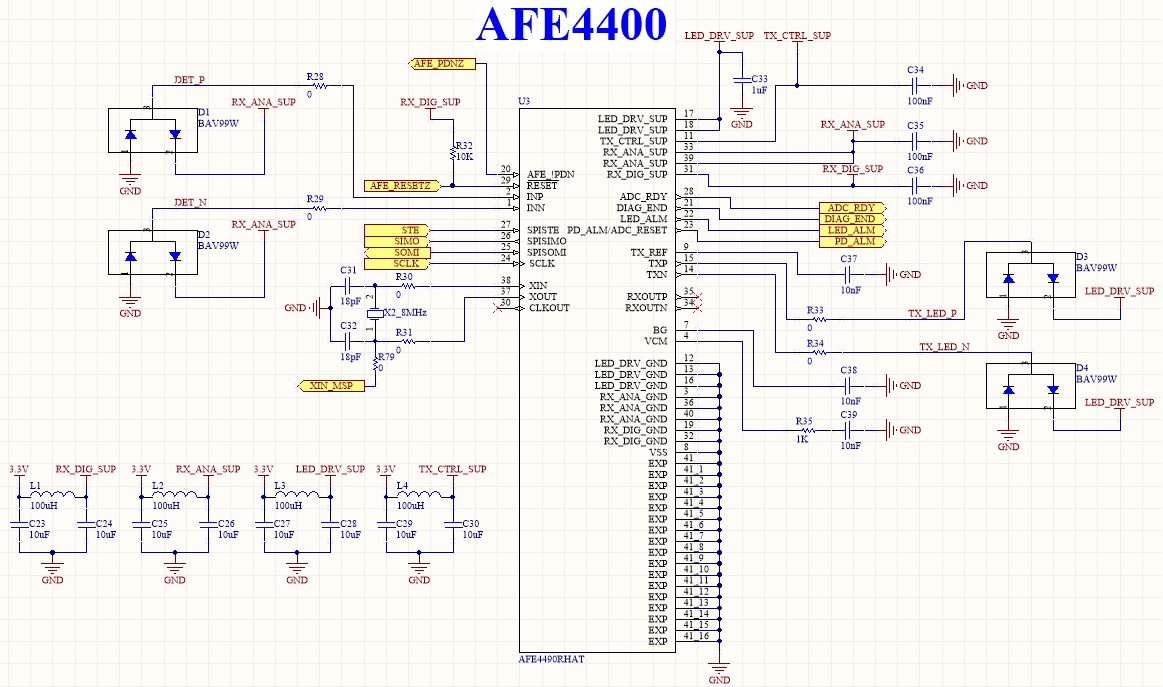 attention...

-
Ask a related question
What is a related question?A related question is a question created from another question. When the related question is created, it will be automatically linked to the original question.

