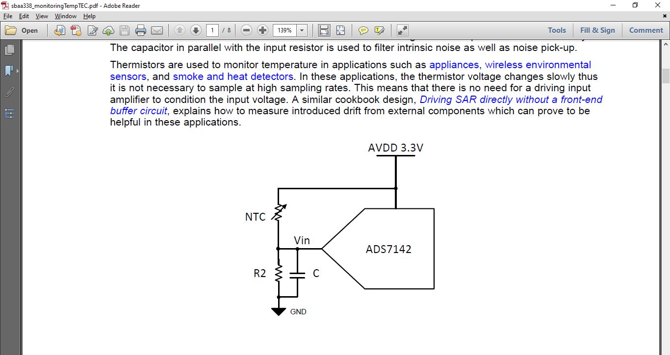
This thread has been locked.

If you have a related question, please click the "Ask a related question" button in the top right corner. The newly created question will be automatically linked to this question.

ADS7142: Use with NTC thermistor for TEC application

Part Number: ADS7142

Hi,

I was going through the application note: Monitoring NTC thermistor circuit with single-ended ADC

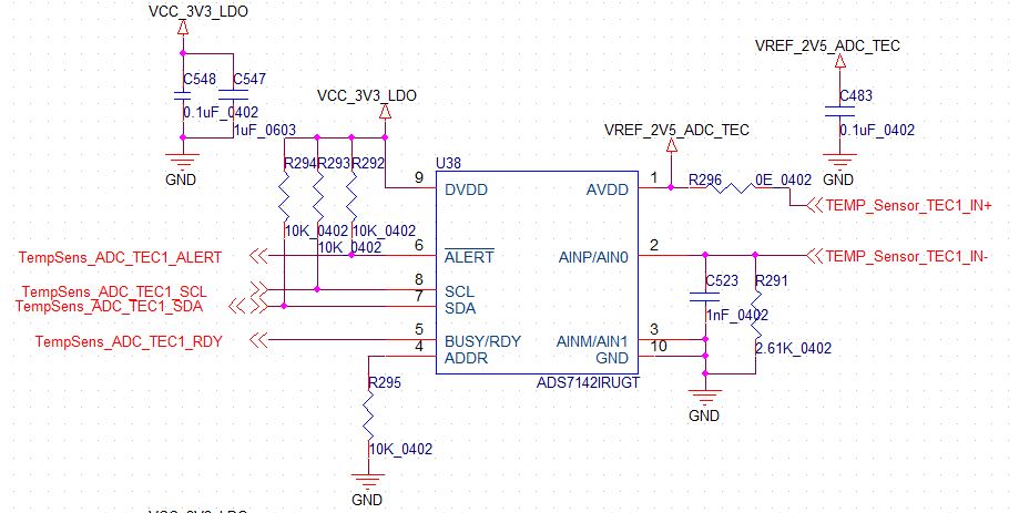
We are using SPAD with TEC in one of our boards. The TEC has an NTC thermistor internal to it.

Below are the specifications of the TEC thermistor(3 stages TEC)

So we would like to know whether ADS7142 can be used for this application of temperature reading?

Please let us know ASAP.

Thanks & Regards,

Nanjunda M

  • Hello,

    The image you tried to upload did not seem to attach correctly, if you could provide the part number, that would be helpful.

    But I predict that it will work fine with the ADS7142

    Are there any issues in particular you are concerned about?

    Regards

    Cynthia

  • Hi,

    I have reattached the image. It does not have a part number as its a custom design.

    The circuit we have designed with respect to the design steps provided in the AN document "sbaa338"

    We were worried about the sensitivity,& measurement reliability as we are taking the sensor input from the TEC through SMA connectors and cable from one board to the other. Also, the TEC may rise to temperatures of about 114 Deg C for most of the duration.

    Will it be able to maintain the sensitivity with cable? How reliable the outputs would be?

    Thanks & Regards,

    Nanjunda M

  • Hello,

    The cables might add some extra capacitance, but that is all dependent on the cable and length of the cable, not the ADC performance. 

    The ADC output will only be as good as the input applied. 

    Looking at your schematic, is R296 populated? I ask because you are connecting the temp sensor positive output to AVDD, while also having a connection to 2.5V. The AVDD pin sets the full scale range of the analog input. Are you sure about this connection?

    Regards

    Cynthia

  • Hi Cynthia,

    1. The cable is of 300mm length. (p/n: CCSMA1-MM-SS402-12). It connects to an SMA on both ends.

    2. R296 is populated.

    3. As per the datasheet, the AVDD is analog supply input for the ADS7142, so we wanted to reduce the voltage range to 2.5V, hence 2.5V is connected.

    The Temperature analog input (from the sensor) we are getting will be in a small current format. So is it wrong to connect to 2.5V? Is there any issue with this?

    Please let us know.

    Thanks & Regards,

    Nanjunda M

  • The ADS7142 measures the voltage across pin 2 (AINP) and pin 3 (AINM). Right now the ADC is only measuring the voltage across the negative sensor output to ground. 

    The sensor positive output measurement is being lost as it is connected to the ADC AVDD. 

    I suggest moving TEC_IN+ to ADC pin 2 (AINP) and TEC_IN- to ADC pin (AINM). This will provide a measurement across the sensor output.

    What sensor are you using?

    The AVDD should be left connected to ONLY the 2.5V

    Regards

    Cynthia

  • Hi Cynthia,

    Thanks for the response.

    As I had mentioned in the previous posts, I'm using a 10K NTC thermistor which is embedded in a SPAD module along with the TEC.

    I have already attached the complete data I have in the previous post, please refer to the same.

    I have designed this looking into the application note: sbaa338.sbaa338_monitoringTempTEC.pdf

    The reference circuitry in the application note is as below:

    So looking at this I have connected my one end of the thermistor to VDD(with 0E resistor and the other end to the input (AIN0).

    Please let me know whether the way I understand the application note is wrong or the circuit provided in the application note itself is wrong?

    Kindly clarify.

    Thanks & Regards,

    Nanjunda M

  • Hi Cynthia,

    Any updates on this?


    Thanks & Regards,

    Nanjunda M

  • Hello Nanjunda

    Apologies for the late response. I hope you were able to move forward. 

    I took a second look at your schematic, and my apologies, it does seem correct. I was misinterpreting the schematic. 

    The circuit in the document you are referencing, uses a 2 pin NTC, and is connected to the ADC as a voltage divider. This makes the output voltage ratiometirc with AVDD, and makes the output be voltage directly related to the temperature, meaning when T goes up, the Voltage measured by the ADC will also go up.

    Regards

    Cynthia

  • Thanks for the reply, Cynthia.

    So from what you said, providing a 2.5V as reference(instead of 3.3V) does not affect the performance of the ADC.

    Q: Is taking the analog input over the cable of 1m is good for this application? Is there any other method we can take the input to the ADC.

    Thanks & Regards,

    Nanjunda M

  • Nanjunda,

    Changing the voltage reference from 3.3V to 2.5 does not affect the device performance. This will change the full scale range. 

    This device has a ground sense capability, which allows for the device to measure the voltage of the input source at far distances. The negative input pin should be connected to ground used by the input source, even if this is far award  or a different board from the ADC. The ADC's ground pin can then be connected to the ground of the board it is located at.

    This can also work the other way, where the ADC can be placed near the input source, using the same method of ground sense as just mentioned. And running the digital lines to the host board, connecting the ADC's ground pin to the host ground. 

    Regards

    Cynthia