This thread has been locked.

If you have a related question, please click the "Ask a related question" button in the top right corner. The newly created question will be automatically linked to this question.

ADS1158: ADS1158EVM + CPU

Part Number: ADS1158

Sorry, the ADS1158EVM-PDK does not work in my environment, so I will change the approach.
I Check the operation only with the ADS1158EVM.
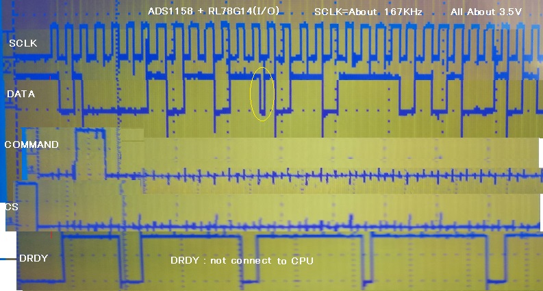
With ADS1158EVM + CPU (RenesasRL78G14), SPI emuration with Didital I / O.
In my program I wrote 0x02 at address 000 and 0x01 at 001. I confirmed the reading.
I could read 2 and 1.
 Other registers are defaults.
I want to read all 16 single-ended channels.
・Send 00110000 command.
-To read status and data, send 24 clocks  for required 16CH and read.
The CHID in the status doesn't seem normal. (CH0 = does not become xxx01000)
(Maybe I just don't understand the English manual)

  • Hi user,

    Are you able to post logic analyzer images showing your communication to and from the ADC? It will be much easier to diagnose the issues you might be having if we are able to see the actual communication process. You will likely need a 4-ch logic analyzer for this request (we usually use the Saleae logic analyzers).

    Please let me know.

    -Bryan

  • I'm sorry, my soft house has only 2ch scope.


    I forcibly synthesized it.
     After turning on the power, I waited enough and slowly performed L/H on the RESET pin.
    ② This time, I set CONFIG1 and 2 to 02H and 83H, respectively. (Reading confirmation OK)
    ③ I wait a few ms after setting START to 10μs LOW.
    ④ I will send the read command in question. As attached.
    I am running on a 3.3V power supply.

  • Excuse me, my soft house has only 2ch scope.
    I forcibly synthesized it. (1) After turning on the power, I waited enough and slowly performed L/H on the RESET pin. ② This time, I set CONFIG1 and 2 to 02H and 83H, respectively. (Reading confirmation OK) ③ I wait a few ms after setting START to 10μs LOW. ④ I will send the read command in question. As attached. I am running on a 3.3V power supply.
    
    
  • Hi user

    You can see from your images that you are not providing 24 SCLKs after DRDY goes low but before the next DRDY transition occurs. I only see ~6 or 7 SCLKs between each DRDY pulse. Therefore, you will not be able to read out 24 bits of data (Status + 16 data bits) given that your SCLK speed is very slow.

    You can either increase your SCLK speed or decrease your sampling rate. Right now it appears you have the DRATE bits in CONFIG1 set to 11b, or the fastest data rate of 23,739 SPS since you have Auto-scan mode enabled.

    Please try one of these options to see if you can get data out correctly.

    -Bryan

  • Thank you.

    There was a limit in adjusting the rate.
    I succeeded in acquiring 16 times for each channel.
    I got a hint and was saved.