This thread has been locked.

If you have a related question, please click the "Ask a related question" button in the top right corner. The newly created question will be automatically linked to this question.

ADS1256 reading 8 channels problem

Part Number: ADS1256

Hi!

I managed to read 0-5V at one channel on ADS1256 (AINCOm=GND).

Now I want to cycle through all 8channels. I have a problem, that after I updated MUX register with a new channel ,the first value read from ADS1256is allways wrong.

This happens even at the startup for first AIN0 channel. When I measured only at one channel this is not important. I simply ignore. But now this makes me troubles.

I need app 100 sps/channel so I set DRATE register value to 0xA1 (1000SPS/8channels=125SPS per channel).

So If I am cycling two times at each channel (becouse I must ignore first reading) I am reducing sampling speed.

In a datasheet it is written that first value should be OK. But this is not in my case.....

The procedure how I am reading data from ADS1256: (this is not exactelly code).

FOR loop (counting channels from 0 to 7) {

--------------------------------------------------------

waiting dataready DRY pin to go low

----------------------------------------------------------

Sending which channel I want to readto MUX register

SPI.transfer(0x51); // MUX register
SPI.transfer(0x00);   // 2nd command byte, write one register only
SPI.transfer(data);   // write the databyte to the register
delayMicroseconds(10);

-------------------------------------------------------------

Sending SYNC command

 SPI.transfer(0xFC);
 delayMicroseconds(10);

------------------------------------------------------------

Senging Wake up command

 SPI.transfer(0x00);
 delayMicroseconds(10);

----------------------------------------------------------

Reading data from ADS1256

 SPI.transfer(0x01); // Read Data 0000  0001 (01h)
 delayMicroseconds(10);
  adc_val = SPI.transfer(0);
  adc_val <<= 8; //shift to left
  adc_val |= SPI.transfer(0);
  adc_val <<= 8;
  adc_val |= SPI.transfer(0);
  delayMicroseconds(10);

 SPI.endTransaction();

} ... END FOR loop

  • Hi Frank,

    What is the master CLK frequency you are using for your system?

    And are you applying 5V to each input as you cycle through the channels

    -Bryan

  • Hi, Bryan!

    I am using 7.86MHz crystal.

    In this moment I have only AIN0 connected to my calibrated 5V signal. All other 7 inputs are "in the air".

    Here are my initialsation for ADS before starting reading analog inputs (maybe helps this info):

    // Reset to Power-Up Values (FEh)
      SPI.transfer(0xFE);  
      delayMicroseconds(10);

    ---------------------------------------------

     SPI.transfer(0x50);// 1st command byte 0101 0000 = 0x00h STATUS register
     SPI.transfer(0x00);   // 2nd command byte, write one register only
     SPI.transfer(0x00);   //write the databyte 000000000 to the register, BUFFER disabled
     delayMicroseconds(10);

    --------------------------------------------------
      SPI.transfer(0x52);// 1st command byte 0101 0010 = 0x02h ADCON
      SPI.transfer(0x00);   // 2nd command byte, write one register only
      SPI.transfer(0x20);   //  0 01 00 000 => Clock Out Frequency = fCLKIN, Sensor Detect OFF, gain 1
      delayMicroseconds(10);

    ---------------------------------------------------

     SPI.transfer(0x53);// 1st command byte 0101 0011 = 0x03h DRATE register
      SPI.transfer(0x00);// 2nd command byte,0000 0000 write one byte
      SPI.transfer(drate_data);   // write the "samling speed" variable
      delayMicroseconds(10);

    ---------------------------------------------------

     SPI.transfer(0xF0);//Self calibration
     delay(2000);//1227ms min at 2.5SPS

    I hope I've wrote all informations you need.

    Thank yu.

  • Hi Frank,

    If the other 7x channels are floating, how do you know what value they should settle to? Or, in other words, how do you know the first sample is "wrong"? Unconnected inputs could theoretically be at any value between the supplies.

    Can you send a logic analyzer shot showing your communication lines so we can see which commands you are issuing, the output on DRDY, the data you are receiving, and to ensure the timing is correct? It will be very hard to know what is going on without being able to see what you are doing. Nothing jumps out as being an error in your code, at least as far as I can see in what you have posted.

    -Bryan

  • Hi, Bryan!

    Now I connected AIN1-AIN7 ti GND.

    AIN0 to calibrated 5V signal.

    And I am cycling through all 8 analog input.

    In fact, now I can not read/get data from AIN0.

    I change  acode a little bit, that the part of the code cylces twice (wait RDY, write to MUX which AIN I want to read, Sync and WAKE up)

    and it wroks. But unfortuantely I still do not get full sampling speed but is a little reduced (I can live with this but anyway, I want to clear the problem if possbile).

    CODE where I am cycling twice:

    for (byte k = 0; k <= 1; k++) {//must do twice!!!
        while (digitalRead(rdy)) {
        //Serial.println(".");
        } ;
      SPI.transfer(0x51); // MUX register
      SPI.transfer(0x00);   // 2nd command byte, write one register only
      SPI.transfer(data);   // write the databyte to the register
      delayMicroseconds(10);

      //SYNC command 1111 1100 (FCh)
      SPI.transfer(0xFC);
      delayMicroseconds(10);
     
     
      //WAKEUP 0000 0000 (00h)
      SPI.transfer(0x00);
      delayMicroseconds(10);
      } // END FOR LOOP

    And unfortunately I do not have a logic analyzer. Hmm...

    EDIT:

    Here is what I am getting as reading AIN0 (connected 5V calibrated signal). Values are in HEX (I think ypu poreffere HEX values...) if I am not cylcling the code twice:

    7F6F13
    14BB
    14C0
    14B7
    14C2
    14BB
    14B2
    14B3
    14BC
    14B0
    14B1
    14B2
    14B0
    14AF
    14BA
    14AB
    14AC
    14B3

    And here is what I am getting if I cycling the code twice:

    7F8578
    7F855B
    7F853E
    7F8699
    7F86C3
    7F8616
    7F86C0
    7F8672
    7F8776
    7F871C
    7F85DB
    7F8620
    7F8587
    7F85AB
    7F84F7
    7F8591
    7F8544
    7F84E7

  • Hi Frank,

    What is your SCLK speed?

    And it seems like from your previous post that things have gotten better, but you are still not getting full speed - is that correct? Are you determining the speed of your device by the timing between DRDY pulses?

    -Bryan

  • Hi, Bryan.

    I hope I understand correctly, you are asking for my SPI speed settings: 1.25MHz.

    How I determne the speed of my device: I am counting how many results I am getting out in time interval:

    At DataRate 0x82 (100SPS/8=12.5SPS per channel) I am getting in 10 seconds 62 samples=6.2 SPS/per channel instead 12.5SPS

    If I remove twice code cycling I am getting 125samples in 10 seconds= 12.5SPS. So there is a difference. But unfortunately I can not use this data

    becouse is allways at one value no matter that I am changing signal from 0 to 5V...

  • Thanks Frank

    In the previous data you just sent, you are just reading a single differential channel (AIN0 and AINCOM) over and over again, correct? Can you send the actual code sequence you use to make just this one measurement?

    Are you using DRDY to determine when new data is available? You should be able to determine your data rate by the time between DRDY going low to the next instance of DRDY going low. You can do this with an oscilloscope by probing DRDY.

    I really think you need to review the communication with an oscilloscope as it sounds like the device is not reading your commands properly. This could be for a variety of reasons, and it will be difficult to diagnose without being able to see the communication procedure.

    -Bryan

  • Hi, Bryan!

    No, not Exactelly.

    I am cycling throught all 8 input channel, but I am printing out only AIN0 value.

    If I set the code to only read AIN0 (0x08), then I have no problem. The first valaue is worng, but later is everything OK..

    Sampling speed is OK, ... except first value.

    But for my application I will need to read 8input channels as fast as possible....

    You can see my code above. There is:

    "waiting dataready DRY pin to go low"

    At this point I am waiting for correct DRDY.

    Ok. I will measure the time DRDY time interval

  • I measured DRDY time interval.

    It shows me 97.75Hz=0.01023s.

    It goes from 5V to 0V for very short time and the rise up to 5V in 0.01023s time interval. And then hold 5V until next interval.

    Data rate is set to 100SPS.

    Then I change data rate to 500SPS and shows me 448 Hz=0.00223s.

    But still I am not getting correct analog value out. It stay at approximately 1658 (HEX) but I am inputting 5V...

    First value is 7F6FB9 (HEX) but all values later are app 1658 (HEX).

  • Hi Frank,

    The timing you have described matches what is shown in Table 14 for multiplexer settling at 100 SPS (98 Hz). But your point is that you are not getting the correct data within that interval?

    Are you sending the output data to a buffer in your controller, or are you still using printf statements to get the data?

    -Bryan

  • Hi, Bryan.

    Sampling speed is OK, but I do not get correct data as you can see from data above... Only if I cycle at the same input channel twice .Then the second read is OK. But then I reduce sampling speed...

    So First I am cycling through all 8 input channels and write values into 8 different variablesl. After I cycle through all 8 channels I print value.

  • Hi Frank,

    I would suggest spending some time with an oscilloscope to verify the values seen on DIN and DOUT match what you are reading from and writing to the ADC. Your waveforms and timing should match what is shown in Figure 19. This is where a logic analyzer would certainly make things easier, but it can be done with a scope.

    If you can probe DOUT and DRDY together, that would be a useful image to share. Try with and without the loop to see if there is any difference. If you could share those images here I would appreciate it.

    -Bryan

  • Hi!

    I have two channel oscilloscope. I think I can manage this.

  • Hi!

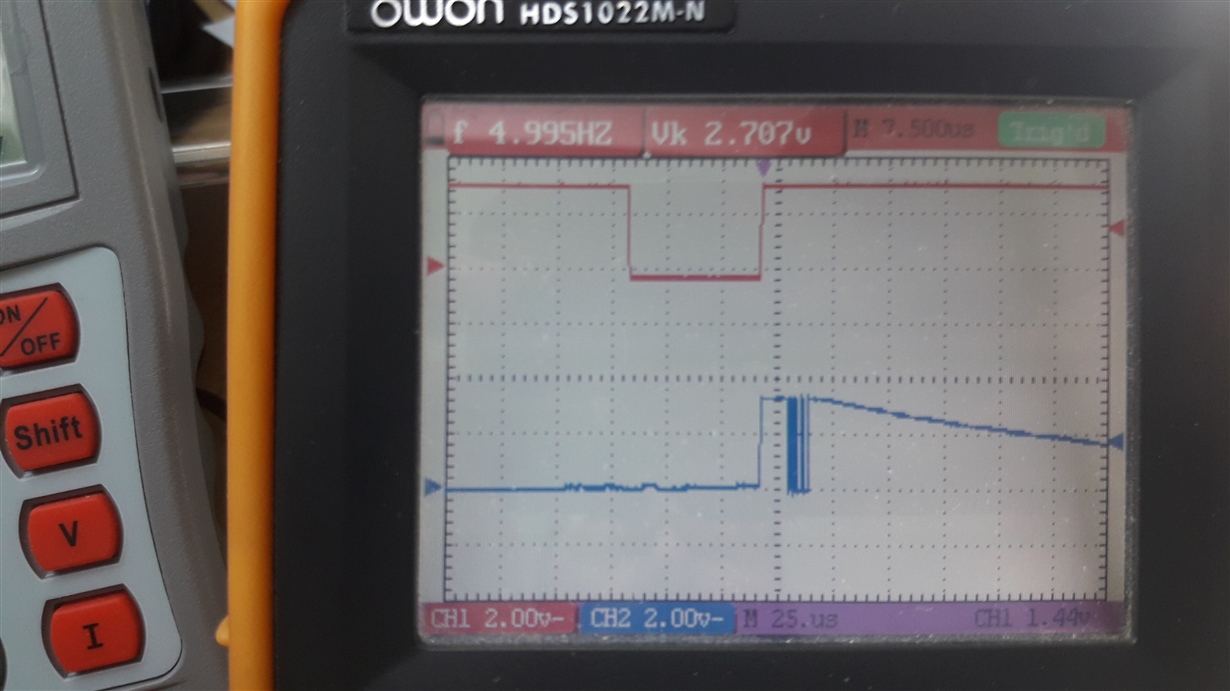
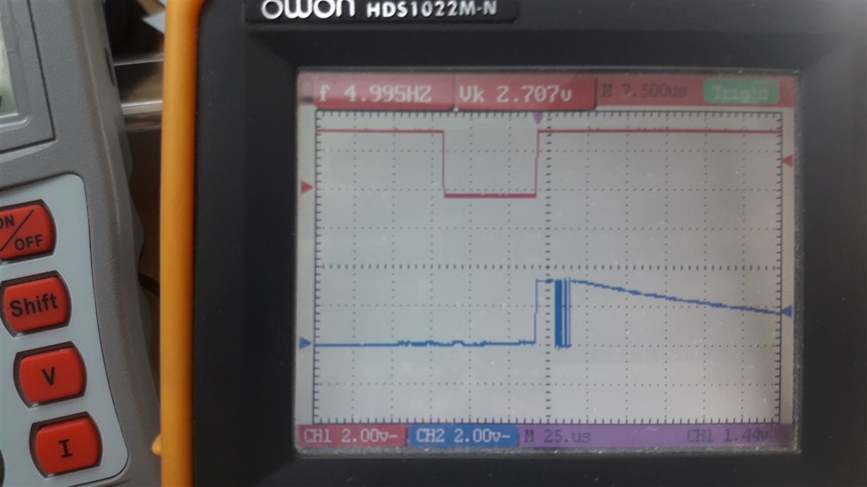
    Here I am attaching pictures. I do not see any difference....

    The red diagram is for DRY pin, the blue is for DOUT pin.

    Screen when values are OK (twice cycling - reading per channel):

    Screen when it is not OK (only once reading from channel):

    Datarate is set to 5SPS .

  • Hi Frank,

    To be honest, these two images look exactly the same, as in one is just a copy of the other. Did you by chance post the same image twice?

    If not, then there is clearly no difference between the two waveforms and it does not seem that the loop is doing anything. This is good news I guess, since it rules that out.

    I would suggest looking at DIN and DOUT together to make sure all of the timing specifications are met. I am also curious why the DOUT line starts to droop in that scope shot. Is there some resistance / capacitance on the SPI line?

    -Bryan

  • Hi!

    I will make new screen shots.... Just to b e 100% sure. Give me few minutes. I will be back.

  • Screen shot when measured values are OK.

    Screen shot when measured values are not OK.

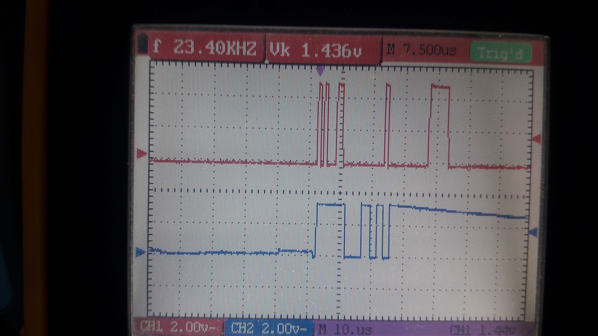
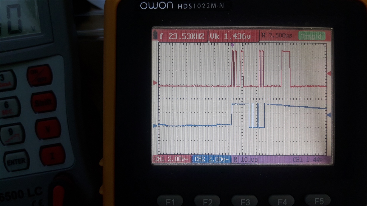
  • Hi!

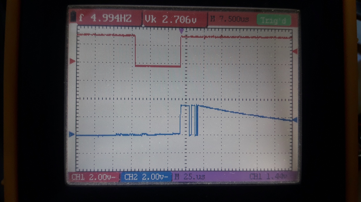
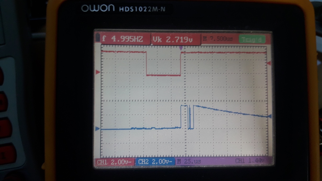
    The red line is Din, the blue line is Dout:

    Screen when measured data are OK (twice cycling per each channel):

    Screen when measured data are  NOT OK (no cycling per each channel):

    Hmm, I think that Din data should be before Dout, not in the same time. If I repeat for each cycle twice then is logical that the second try will be OK.

    But I do not know why this happens.... I will try to increase pause between (MUX,SYNC, WAKEUP statement group) and READ statement...

  • Hi Frank,

    In the last set of images, it looks like your DIN line uses a 5V logic level while the DOUT line is at 3V (since they are both on the same 2V scale on the scope). Is that the case? This could certainly cause issues since the device is expecting logic levels at 3V and might not interpret 5V logic correctly.

    In either case though, the data appears to be the same, likely close to a full-scale reading. So this appears to have something to do with the way you are getting and storing data from your system.

    -Bryan

  • Hmm. It could be. I am using micro controller with 5V logic....

    EDIT:

    I checked in the user manual for ADS1256. There is written ,that ADS1256 is 5V ISP tolerant

  • Hi Frank,

    Yes, the ADS1256 is 5V tolerant, but you are supplying DVDD with 3.3V. This could certainly cause issues when logic levels are not the same.

    You could apply 5V to DVDD on the ADS1256, or use a level translator to make sure your IO logic is at the same level for both MCU and ADC.

    I also agree that you should not be seeing data on DOUT and DIN simultaneously if you are following the command pattern shown in Figure 19. Maybe that would make sense when you are running the loop twice, but it should not be the case when you are only running the loop once.

    -Bryan

  • Hi, Bryan.

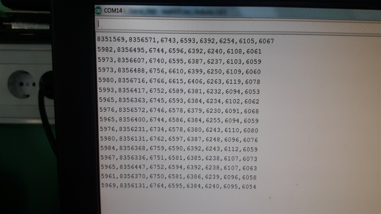
    Before I make a voltage shifter I made a screen shot of reading all 8 channels.

    AIN0 connected to 5V all other channels connected to GND.

    It is visible that in first iteration ADS1256 send out value for 5V for AIN0 and AIN1 channel.

    In next iterations it allways show for AIN1, despite it is physically connected to GND.

    Dose this tell the same as you mention above or you can see something else?

  • Hi Frank,

    Are you sure you are not just reading AIN0 twice initially? Then it makes sense, if the 8356xxx values are all AIN0, since this is close to full-scale, and the rest of the 7 values are AIN1-AIN7, which are all close to GND.

    The challenge here is knowing what commands have been decoded by the ADC and when they have been decoded. Just looking at the output data doesn't tell you much since you are unable to determine which channel each data point corresponds to. But the data looks valid to me given your input conditions, assuming the full-scale values correspond to AIN0.

    Can you apply test voltages to the other channels to see if the full-scale reading follows the channel change? Or apply 5V to AIN0 and 2.5V to AIN1 and see what happens?

    -Bryan

  • First I will connect DVDD to +5V. Are you sure I can not burn something?

    In user manual it is written Digital supply 1.8 to 3.6V..

  • Hi Frank,

    My apologies, I am doing too many things at once. Yes, please stay with 3V supply, for now you can use the circuit as is (5V logic on the MCU, 3V logic on the ADC).

    Please try the other input tests I suggested however.

    -Bryan

  • I apply 5V signal to separately to all 8 channels. The result is always shifted for one place to the left..

    If I apply 5V to AIN0, I see results at 2nd place instead 1st place. If I apply 5V to AIN1, I see result at 3rd place instead 2ndplace,....

    If  I apply 2.5V I see values app. 4174880.

    At the end, I can live with this situation, I simply shift results for one place to the right and it is OK. No sampling speed reduction (no needs for second cycling for each channel).

    I have another question but I do not know should I open a new thread or stay in this.

    It is about accuracy.

    As you can see I am applying 5V calibrated signal. I am using high precision 2.5V voltage reference ADR431B with 2.5V +/- 1mV.

    I expect values more close to 8388607. The difference between measured and theoretically value is app. 37897. What do you think about that?

    If you remember (look the code above) I perform self calibration before start reading.

    Even values when I have input ports connected to GND seems for me too high (app 6000).

    What is your opinion about that?

  • Hi Frank,

    Are you still running the loop twice for this data? Or have you removed the loop such that those commands only run one time now?

    -Bryan

  • I remove the loop. So I am reading now channel only once.

  • Thanks Frank, so it seems like this issue is resolved, correct?

    If so, can you please ask your accuracy question in a separate thread? That way if another person has your same question they will be able to navigate to the correct thread.

    -Bryan

  • I will do in this way. For me it is OK.

    Ok. I will open a new thread.