This thread has been locked.

If you have a related question, please click the "Ask a related question" button in the top right corner. The newly created question will be automatically linked to this question.

DAC80501: SPI Communication not working

Part Number: DAC80501
Other Parts Discussed in Thread: ADS1262,

Hey there,

I need some help with debugging a project using the DAC80501Z in VSSOP package, which seems to be the main difference to other SPI communication related posts.
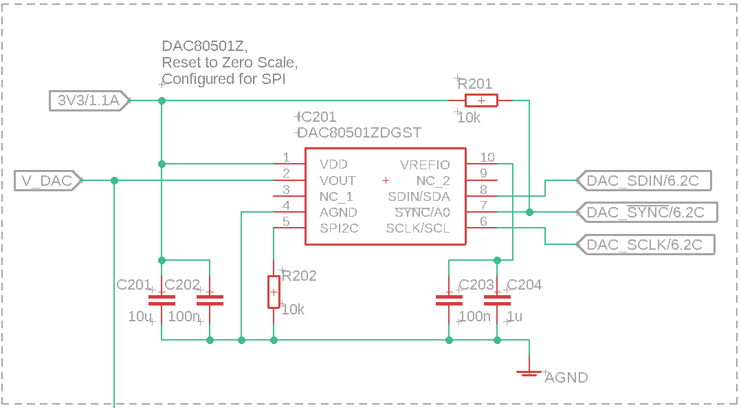
See the schematics below. The 3 SPI Lines are connected to the Microcontroller via 47R Resistors. The output is connected to an OpAmp Input via a RC-Lowpass (715R, 1nF).

Unfortunately, the DAC does not show any sign of receiving any SPI commands. I tried disabling the internal reference as often suggested in these forums, but writing 0x03 01 00, the reference Voltage still remains at 2.5V. I also tried reset command 0x05 00 0A, set the GAIN register to REF-DIV 0 and BUFF-GAIN 0 with 0x04 01 00 and send multiple DAC codes like 0x08 80 00. Whatever I do, I fail to detect any changes in the DAC state. The Output always stays at 0V.

I already tried SPI speeds from 1MHz to 50MHz and SPI modes 1 and 2 (falling edge detection). With an SPI capable oscilloscope, I checked the transactions, which seem perfectly fine: Clock idles, Chip Select goes Low, the 3 Bytes are transferred, Chip select goes high again. I also tried like 2 µs delays between Chip Select and the byte transactions to no effect.

On the same SPI line, there is also an ADS1262, with which the SPI communication works flawlessly (8MHz, SPI Mode 1). It does not seem to interfere with the DAC communication, the MISO line stays low.

Two hardware prototypes are manufactured so far, and both show the same behaviour. Electrical tests do show that nothing is connected to somewhhere that it should not be. Maybe the 10k pulldown resistor value on SPI2C is to great and thus, the device bever enters SPI mode?

Help would be greatly appreciated.

  • Hi,

    Somehow, I am not able to see the attached schematics. Can you please post it one more time?

    What's the supply voltage you are using? Internal or external reference? Please share oscilloscope shots of the SPI frame as well.

    Did you try to read back any default register values to check the SPI frame is fine?

    Regards,

    AK

  • Sorry, the schematics must have gone missing. I will append them again.

    The supply is 3.3V. I use the internal reference. I am aware that I will need to adjust the GAIN register to get any output due to supply headroom.

    As far as I know, the DAC80501is write-only in SPI mode. There is no MISO function pin or anything mentioned in the data sheet.

    I may try to supply oscilloscope screenshots tomorrow.

    EDIT:

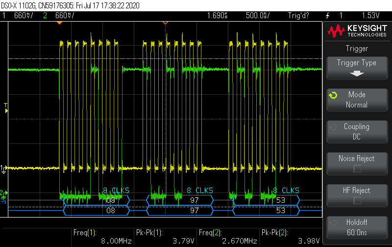
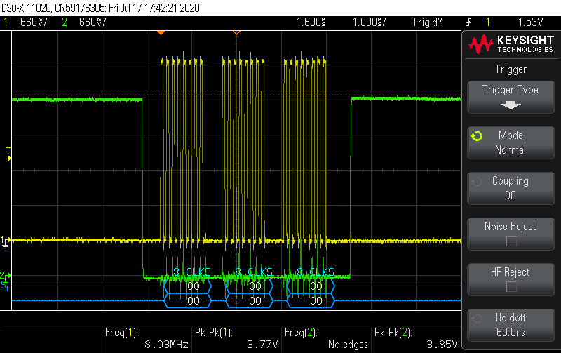
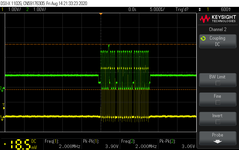
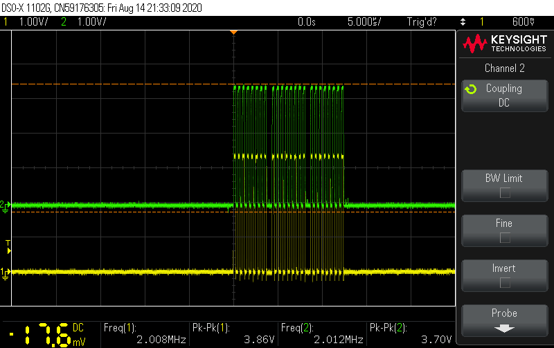
    Here are oscilloscope pictures, directly taken on the DAC's pins, 8 MHz, SPI mode 1. Written Code is 0x08 97 53, which should set the DACs output voltage above 0, but fails to do so.

    SDIN and SCLK:

    !SYNC and SCLK:

    Thanks in advance for any help on this problem.

    Unfortunately, I wont have access to the lab and wont be able to supply any further screenshots until August.

  • Hi,

    I am not seeing any issues with your timing diagrams. The fact that you are getting 2.5V at pin 10 shows that device is powered up and active.

    One debug I can suggest is to remove 10K from SPI2C pin and connect directly to ground and check. Ideally 10K to ground should be fine. I don't have access to lab as of now to check these. Please have a look at these options for debug.

    I will follow up with you on this thread as soon as I go to lab and verify these.

    Regards,

    AK

  • Thank you for the suggestion. I tried it and replaced the 10k pulldown with a zero Ohm Jumper, but unfortunately, to no effect. Still no output and still not able to deactivate the reference.

    I checked some more design details. The 3.3V DAC Supply needs less then 1ms to fully stabilize. All SPI bus activity starts 2 seconds after start-up, so the DAC should be ready. I also experimented with lots of delays after startup or in between transactions to no avail.

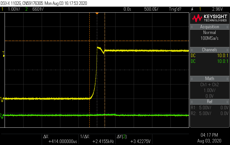
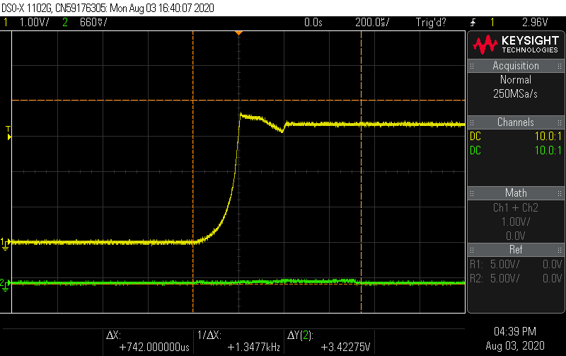
    I also monitored the SPI2C pin, but there are no glitches or anormalities with either 10k or zero Ohm. It stays at ground level:

    So far, most people seem to use the WSON-8 Package. Could the issue be related to the use of the 10 pin VSSOP Package in the design? When you are in the lab, could you please confirm the Pin locations on the VSSOP version?

    Regards

  • Hi,

    There is nothing related to package whether using VSSOP or WSON.

    Since your supply is 3.3V and internal reference is 2.5V, initialization code should do the following.

    1. Power up DAC

    2. Set REF_DIV bit to 1, so that internal reference is divided (by default REF_DIV is set to 0)

    3. Set BUF_GAIN bit to 1, so that Gain will  be 2, output voltage will be from 0 to 2.5V

    Are using synchronous or asynchronous mode? 

    Regards,

    AK

  • I use the following initialization code, as stated in the opening post:

    0x05 00 0A    // Soft-Reset
    Delay 200ms 0x04 01 00 // RefDiv 2, Gain 1 -> 1.25V max. Output 0x08 43 21 // some DAC code, ~328mV

    I use the default dac mode (asynchronous mode, should update immediatly).

    But even with a faulty initialization, I should be able to turn off the internal reference with the command 0x03 01 00, but I can't.

    Regards

  • Hi,

    I have used the exact same initialization code to test this.

    I am getting output without any issues. Can you please check what is the current drawn from 3,3V supply? Also please check your soldering of the digital pins once more. if possible try to probe the signal on the DAC pins, not on the solder joints, that way we can be double sure about the connection.

    and please disconnect any other device which is using this supply when you are doing this experiment.

    Regards,

    AK

  • Hey,

    as you suggested, I checked all DAC pin connections again, but could not find any issues. Also checked for crossconnections, but nothing there as well. Everything was of course measured directly from the DAC pins (as were the oscilloscope images posted previously).

    Unfortunately, I cannot measure 3.3V current directly. The Power supply is sequenced from 12V DC (switching type, 2A) to 10V DC (LDO TPS7A4501, 1.5A) to 3.3V (LDO TPS7A4501, 1.5A). I can only give the total current draw from 10V, which is about 25mA, way below any power limit. Also, nothing is getting hot. 3.3V is buffered with about 100µF of capacitance and rockstable, I cannot see any drops on the power line or something. All other 3.3V devices are working, as is the internal DAC reference.

    I might not be able to detach the other devices from 3.3V (it is a pre-production PCB, more then 10 other SMD ICs on this line, won't get all those off without damage to PCB/other components). I will make one more prototype with minimal components attached and report back.


    Could it be that the serial interface of all DAC units was damaged during soldering, but their reference still powers up? I mean, the devices have power, ground, and the digital signals as received on the pins are in good shape. SPI2C pin is at ground level all the time. And yet, nothing I send is processed at all. It seems unlikely that multiple units are damaged the same way, but sometimes, you get unlucky.

    Thanks for your help so far!

    Edit: Just checked on the ADS1262 again, which is on the same SPI interface (mode 1, 8MHz) and uses the same 3.3V supply, all works fine.

    Edit on August 7:

    I now have a total of 4 prototypes, 2 of them with just the minimal amount of components to test the DAC functionality. All connections and signals are verified to be correct. Only one of them worked for about half an hour after assembly, but has stopped working since. All DACs have the same behaviour: the reference still powers up, but no commands are processed at all. I am certain that their serial interfaces got somehow destroyed. In the Oscilloscope shots from the SPI signals the lines have pk-pk values of up to 4.0V, measured on the DAC pins. I will investigate this and report back, I am currently waiting for more chips to test solutions on.

  • Hi,

    Let us know the results. I am curious to know what happened.

    Measuring 4V on the IO lines shows something weird happened, But highly unlikely that device might have damaged. And you said it worked for half an hour, that seems strange.

    Regards,

    AK

  • Hey,

    I finally got to test the new batch. I replaced the 47R resistors on SPI lines with 390R. Now, it seems that I do no longer kill the DACs before they can answer. 

    But the Communication is still really awkward. Sometimes it works flawlessly, then again the DAC does not respond for 1 second, or for minutes. Sometimes, a reset command works, sometimes nothing works.

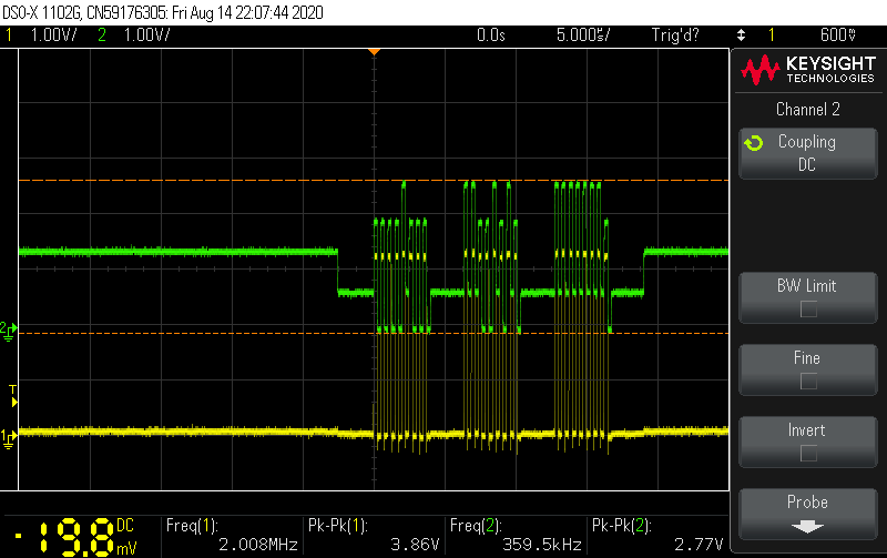
    Sometimes, I could observe weird glitches on the SPI lines, but only on the DAC side of the SPI resistors (signals are the same on the resistor terminals and DAC pins). They look like this (SCLK shown, yellow - MCU, green - DAC):

    These repeat an arbitrary number of times, roughly fitting the response/no response pattern, and sometimes return to a readable pattern on the DAC side like this:

    This happens with any DAC output value. Although the above Images look like I accidently connected SLCK and CS with the oscilloscope probe, I can assure you that this was not the case. I can get the same arbitrarily changing patterns when measuring on the resistors. Also checked the new DACs for electrical connectivity, all things good, no pins/pads etc are interconnected.

    On the power sequence side, I also took extra care that no communication on SPI occures before the DAC receives 3.3V. The datasheet implies that this may damage the DAC (its SPI pins are rated Vdd + 0.3V). But in my testing, I could not get a working DAC to get destroyed by SPI communication while its Vdd is still at GND (for seconds).

  • Hi,

    The second plot data looks to me as if you have some kind of reflection on the SCLK line. What's the frequency of SCLK?

    Can you reduce the SPI operating frequency and do continuous check to observe for any failures?

    Regards,

    AK

  • The frequency is now 2 MHz. I am preparing a long term test setup at the moment and will also use much lower frequencies there.

    I believe that the issue is also design-related, so I want to share more details: The SPI isolation resistors are placed right next to the microcontroller socket. SPI lines go about 3cm on the Main-PCB to a FFC-connector with a 10cm straight FFC cable. This connects to the DAC-PCB; the DAC is right next to the FFC connector. When I measure with the oscilloscope on the DAC-Pin and on the DAC-Terminal of the resistor on the Mainboard, I always receive the same signals.

    I always checked for the cables conducting, and always measured less then 1 Ohm from resistor to DAC-Pin. Interconnections never occured. I already made Bode-Plots from the connection lines, but could not observe anything odd up to 20MHz (I don't have access to a higher frequency generator right now). Starts with 0dB and shows low pass behaviour at MHz frequencies, with 390R the cutoff frequency is about 10MHz. This indicates about 40pF of capacitance on the lines, 10pF of which are on the DAC Pins according to the data sheet.

    Right now, all 4 DAC-PCBs seem to work, at least part time, but only with Mainboards with 390R SPI line resistors. I do have the suspicion that the connectors are part of the problem. 

    I will report back when I have more data.

  • Hi,

    Thanks for the update. I will wait for your data.

    Regards,

    AK

  • I found a solution now, that works with communication at 2 MHz. I logged several million data points over the last week with each prototype, and everything is working as expected now.

    1. The signal glitches were not DAC-related. They came from the 0.5mm FFC-connectors. Our manufacturing seems to have some trouble with the specific model we used. Despite resistance measurements being okay, there seemed to be some defective contacts. I was able to rework them.

    2. The SPI lines somehow need 390R resistors. Not-working PCBs with 47R or 120R could be fixed just by replacing those with 390R. I always changed all resistors, so I don't know if it is maybe only necessary on the Chip Select or something. The Microcontroller used is a SAMD51. Note that, with 390R @ 3.3V, both the DAC80501 and the SAMD51 are below their respective current limit of max. 10mA, while 47R or 120R theoretically exceed it. It really should not matter on a voltage driven interface, but there is definitely something odd going on.

    Anyway, now it works at last!

    Thanks for your assistance!