


Other Parts Discussed in Thread: ADS1219
Hi
My client wants to implement DC Meter using ADS122C04.
There is a problem with ADS122C04 operation.
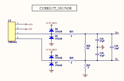
(-) ADC RAW data is read correctly at low current. (1A ~10A)
However, at the high current, ADC RAW data are outputted with a non-regular value. (11A ~70A)
The customer is asking for a solution.
1. Please review the circuit diagram
2. review the Configuration Register
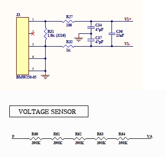
<Bipolar analog power supply>
Voltage measurement range: 450V to 550V
Current Measurement Range : (+)0.5A to 120A / (-)0.5A to 120A
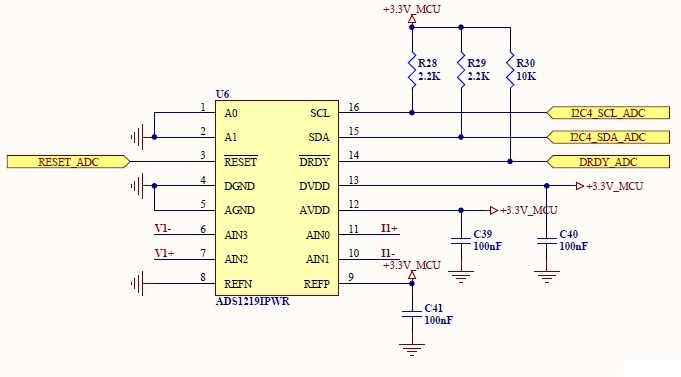
Configuration Register
