This thread has been locked.

If you have a related question, please click the "Ask a related question" button in the top right corner. The newly created question will be automatically linked to this question.

ADS1292R: how to finetune Respiration phase RESP_PH[3:0]

Part Number: ADS1292R

Hi, I'm testing the respiration function of ADS1292R on our board. The schematic of respiration is same with TI demonstration kit.

AVDD=2.5V and AVSS= - 2.5V

ADS1292R register setting is:

ADS1x9xR_Default_Register_Settings[15] = {
                //Device ID read Ony
                0x73,                         // Device ID read only
                //CONFIG1
                0x04,                         //2000 sps  @config 1
                //CONFIG2
                0xB0,                         //4.03V reference, reference buffer enabled @config2
                //LOFF
                0x10,                        // @loff control register
                //CH1SET
                0x00,                        //gain 6 normal operation @ch1set
                //CH2SET
                0x00,                        //gain 6 normal operation @ch2set
                //RLD_SENS
                0x2C,                        //@rld_sens
                //LOFF_SENS
                0x00,                        //loff disabled @loff sens
                //LOFF_STAT
                0x00,                        //@loff_stat
                //RESP1
                0xCA,                        //resp ciruit mod/demod on @resp1
                //RESP2
                0x03,                        //@resp2
                //GPIO
                0x0C
};  

When I test it on the patient (I'm the patient since I do not have patient simulator),

Channel 2 is connected to RA and LA for ECG. Channel 1 is for respiration and share the electrodes with channel 2.

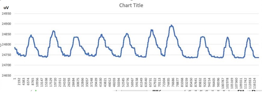
I can get the respiration waveform as this:

seems the function of respiration is good.

But when I change the register setting of Respiration phase RESP_PH[3:0] , there is no obvious difference on the AC portion of the respiration waveform.

the only difference is the DC of the waveform. DC voltage of the waveform increase from 15mV to 49.3mV when Respiration phase RESP_PH[3:0] change from 0000 to 1111. 

so it looks fine regardless how RESP_PH[3:0] is configured.

My question are:

1: whether the DC voltage increasing by changing Respiration phase setting is expected? If possible, could you please help explain the theory behind it?

2: Is there any criteria that I can use to evaluate the setting of Respiration phase RESP_PH[3:0]?

Thanks.


  • Seems the waveform picture can not be displayed. paste it again:

  • Try it again...this is the respiration waveform I got:

  • Hello LX,

    Thanks for reaching out.

    As you increase the respiration phase setting, the gain error reduces.

    This is illustrated in the application note: https://www.ti.com/lit/an/sbaa181/sbaa181.pdf

    Please refer to section 3.4 and figures 9a and 9b.

    As the modulated signal transitions when the block signal is removed, a negative glitch remains on the output and this introduces a gain error.

    As the block signal is increased by increasing the respiration phase setting, the gain error reduces.

    To validate the DC signal output and find the respiration phase setting, you could use a known impedance and sweep through the respiration phases to find out which phase setting gets you closer to the expected DC output (refer equation 1 in the app note).

    Regarding the criteria to measure the respiration phase setting, you may refer to the channel 1 noise as the baseline impedance, gain, and phases are swept. This is explained in section 9.2.2 of the device datasheet.

  • Thanks Praveen,

    I did some testing in these days based on your suggestion.

    topic 1: To validate the DC signal output and find the respiration phase setting, you could use a known impedance and sweep through the respiration phases to find out which phase setting gets you closer to the expected DC output (refer equation 1 in the app note).

    LX: I used a 500ohm resistor as a known impedance. so based on equation 1 in the app note, the expected DC is: 25mV  (VREFP-VREFM=4.033V). 

    I got about 25mV when the phase setting is 22.5 degree (@ 32KHz) .

    My question is: whether 500ohm is good enough to simulate the patient? will the patient lead to more phase shifting? 

    actually I also tested it with a 7.6KOhm resistor, the expected DC is 348mV, but I could only get about 240mV with this setting. looks like it is non-linear, May I know if this nonlinearity is expected? 

    topic 2:Regarding the criteria to measure the respiration phase setting, you may refer to the channel 1 noise as the baseline impedance, gain, and phases are swept. This is explained in section 9.2.2 of the device datasheet.

    LX: since the test circuit is Figure 69 of the datasheet is standard circuit, are we expected to repeat same test as in the section 9.2.2 and 9.2.3 of the device datasheet?   

    As recommend in section 9.2.2 of the device datasheet, if I set respiration phase to 112.5° (32K, Gain=3), the DC level I got is 33mV  with a 500ohm resistor.

    This is different with result in topic 1.  May I know which result we'd better to follow?

    Thanks.