This thread has been locked.

If you have a related question, please click the "Ask a related question" button in the top right corner. The newly created question will be automatically linked to this question.

DAC81416EVM: What to do when SPI clock frequency goes beyond 50 KHz

Part Number: DAC81416EVM
Other Parts Discussed in Thread: USB2ANY, DAC81416

Hello,

I'm evaluating the DAC81416EVM board. So far interfacing the DAC with an external microcontroller works fine. I manage to W/R register and output voltages on different channels. I compared performances by using the USB2ANY TI interface. I realise that the SPI clock provided by this interfaced is by default set to 45kHz while the speed of ths SPI clocl of my board is around 322kHz.

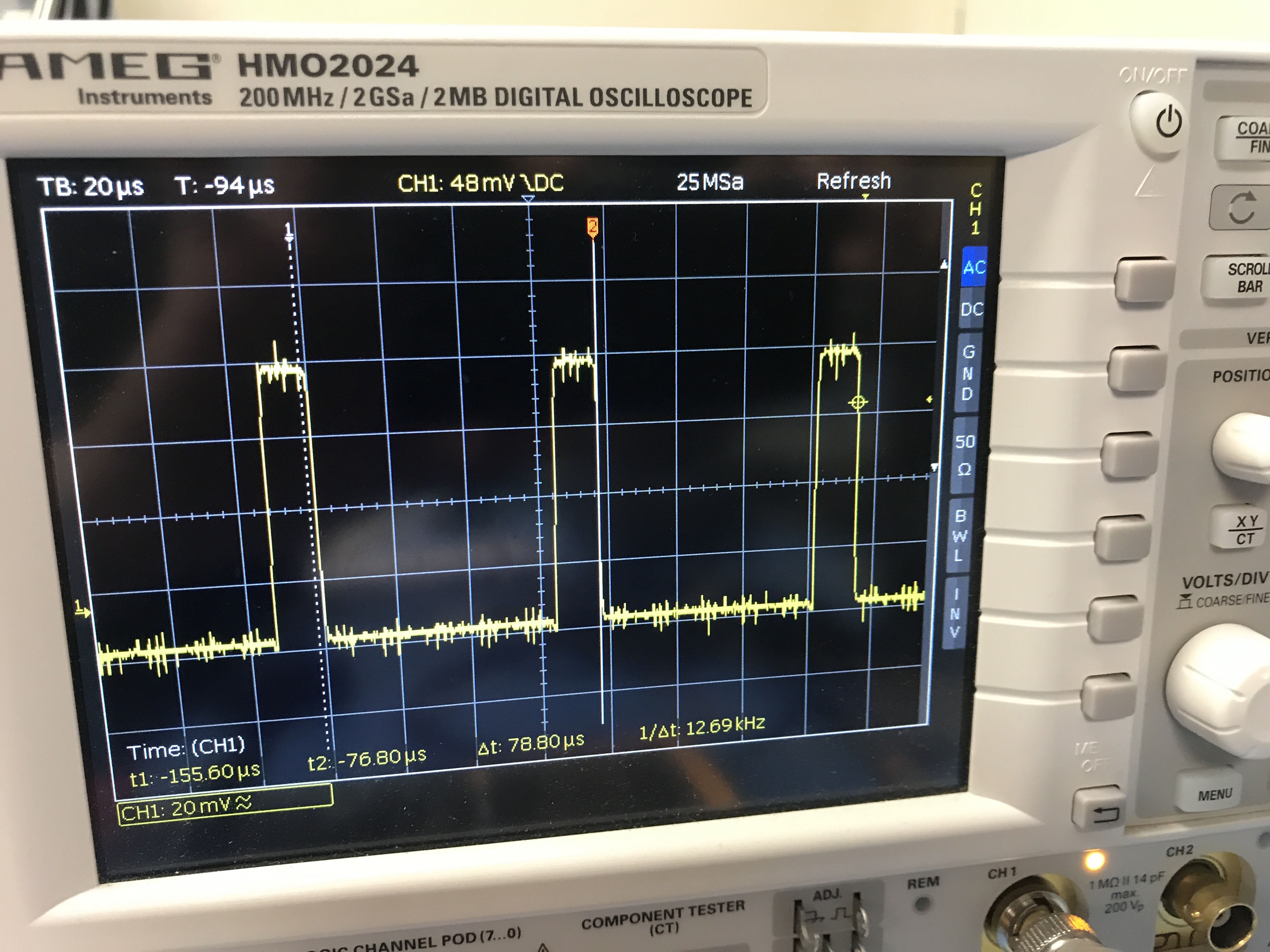
My question here is how to mange to reduce interferences induced by the SPI lines on the outputs when operating abovee 100kKz. I have a strong interest to use this DAC with a SPI clock of 20MHz.

Do you have any recommendation of length of cable that should be used in this condition?. Is there any termination network that you recommend that help to reduce the spike produced by the clock pluses when running at high speed?

best regards,

Fausto

  • Hi,

    USB2ANY is slow interface. You can definitely use DAC81416 with 20MHz SPI without any issues.

    Please take care of the layout in terms of analog and digital grounds to avoid coupling from digital signals to sensitive analog signals.

    Also in the SPI lines have series termination resistors from the source side ( I mean whoever is driving the DAC) . I recommend having 22 to 33 ohms, You can increase this values up to 50 Ohms, But please verify the SPI transactions.

    Other thing is to operate the DAC with lowest possible DVDD voltage.

    NB:  Always careful layout first to avoid any coupling issues.

    Regards,

    AK

  • Hello,

    thanks for your quick reply.

    I tried a microntroller that provides SPI clock frequency of around 15MHz. The communication with the DAC works fine, nevertheless, the generated signal on one of the outputs of the DAC has some effects from the clock. A sort of small spikes of 10mVpp amplitude (see attached picture). Unfortunately, the only way I have to connect the SPI lines are via 4cm length cable. I tried to add the termination resistor on the slave side. Although the SPI transitions look good  I will tryto swicth them to the master side and see if something changes for better.

    As you mentionned this coupling from digital signals into the DAC output impairs me to use signals less than 10mV amplitude.

    As for the DDD voltage, I operate it with 4.5V which corresponds to the minimum recommended.

    best regards,

    Fausto

  • Hi,

    Somehow the attachment is missing in the post, Can you please attach the same?

    Series termination should always be on the master side, not on the slave side. For SDO, it should be near to slave, all, other signals place near to Master side.

    Regards,

    AK

  • Akhilesh K said:

    Hi,

    Somehow the attachment is missing in the post, Can you please attach the same?

    Series termination should always be on the master side, not on the slave side. For SDO, it should be near to slave, all, other signals place near to Master side.

    Regards,

    AK

    Hello,

    thanks for your reply. I have attached the image of the signal I measured at one of the DAC outputs. I have followed your advice of placing series resistors of 33 Ohm at the master and slave side depending of the SPI line. The amplitude of this interference have been reduced but not completely eliminated. I think in order to get rid of theses peaks is to have both the mircontrontroller and the DAC in the same PCB.

    best regards,

    Fausto

  • Hi,

    Yes, if you want to completely eliminate (some amount of coupling will be there), both has to be on the same board and layout has to be done with utmost care.

    Regards,

    AK